
LGX Mosquito for SideWinder & Genius
Legacy Store Offer : Value of the Mounting Set
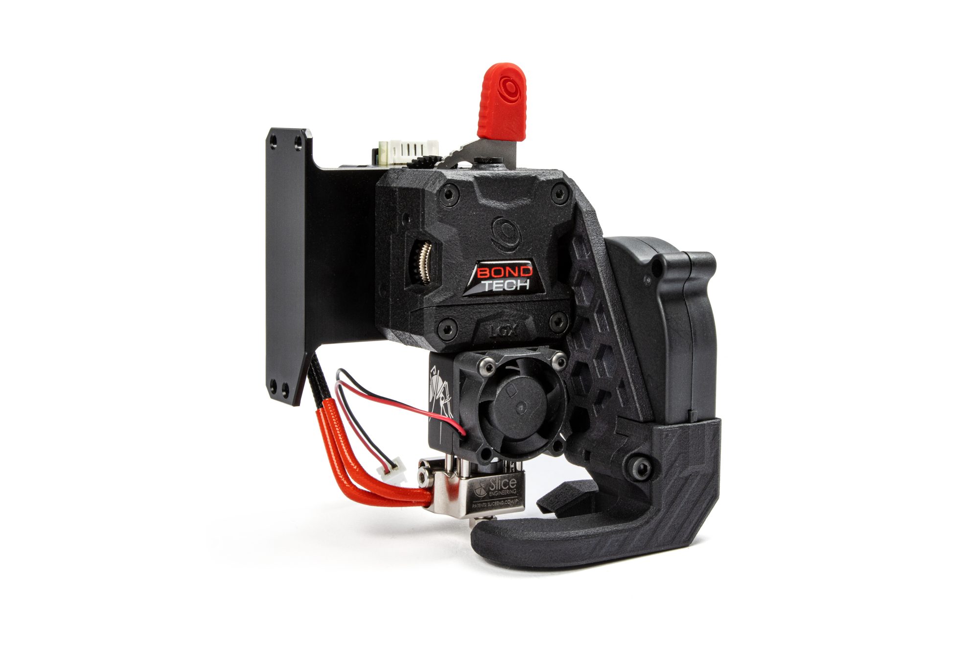
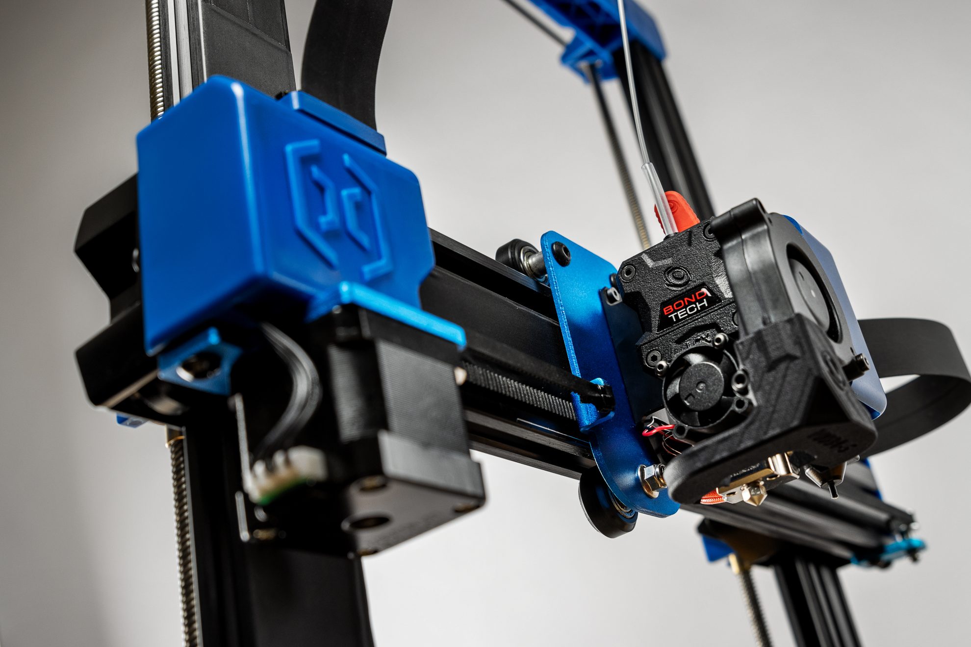
Upgrade the most important components of your Artillery – the extruder and hotend – with Bondtech’s reliability and Slice Engineering’s thermal performance.
This is a 1.75mm filament direct extruder setup to use on the following:
- Artillery Sidewinder X1
- Artillery Sidewinder X2
- Artillery Genius
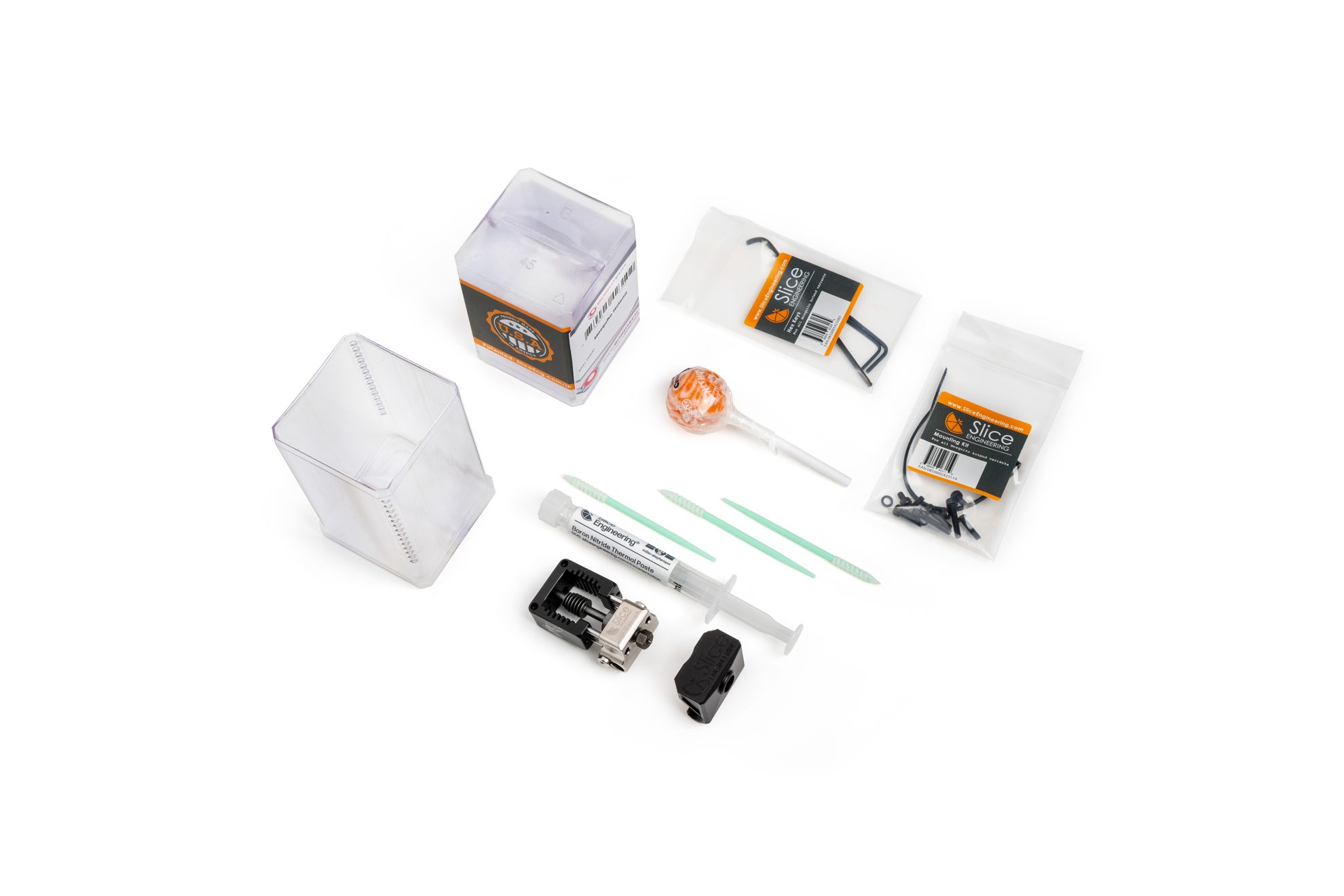
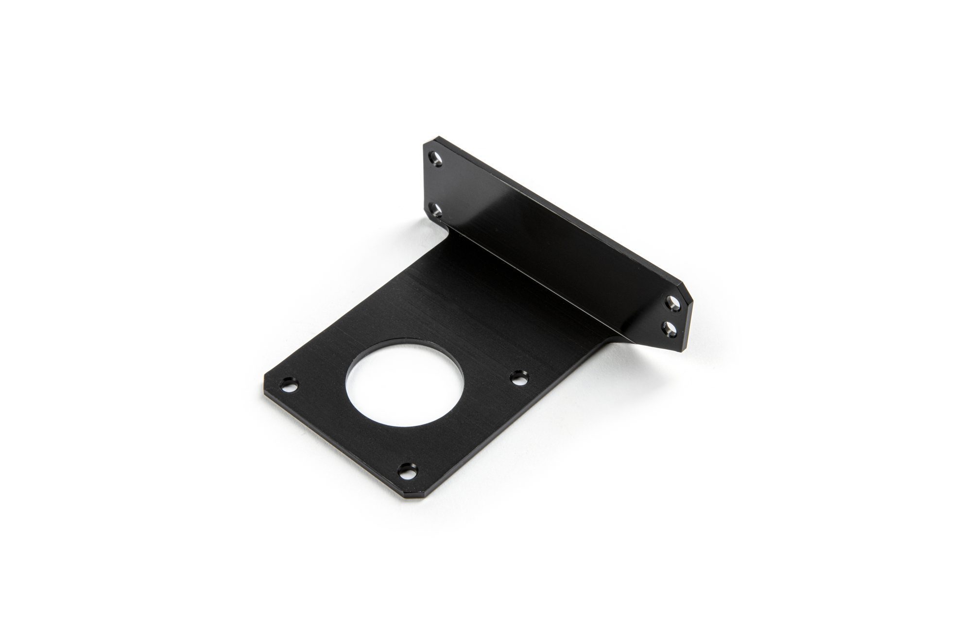
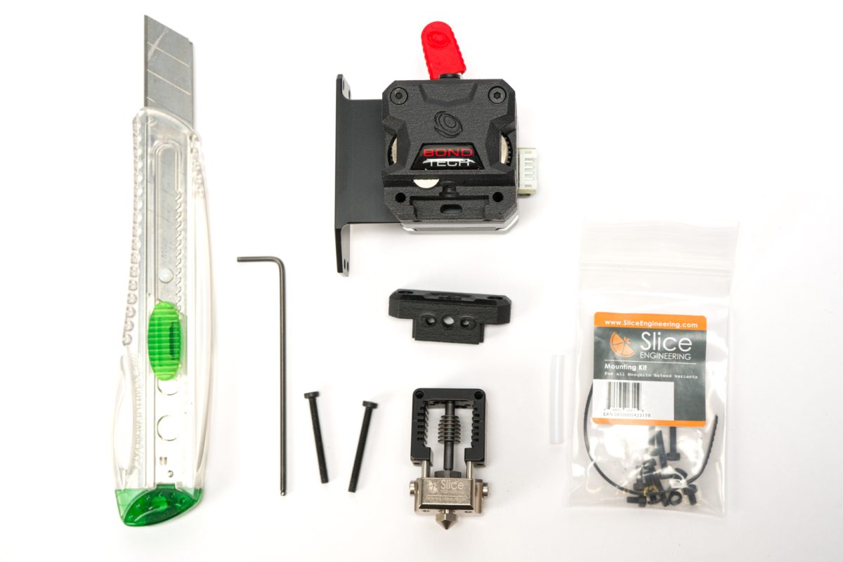
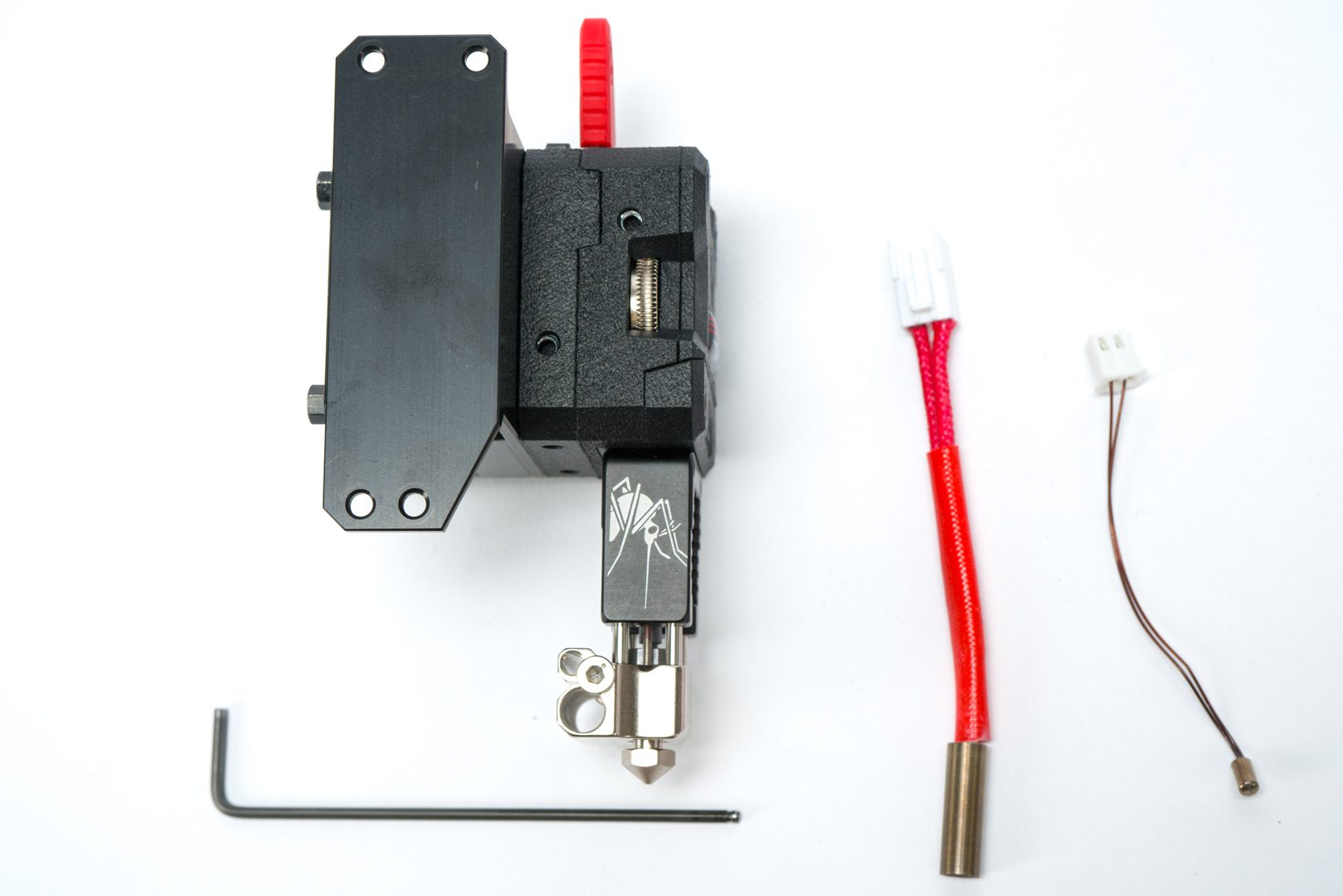
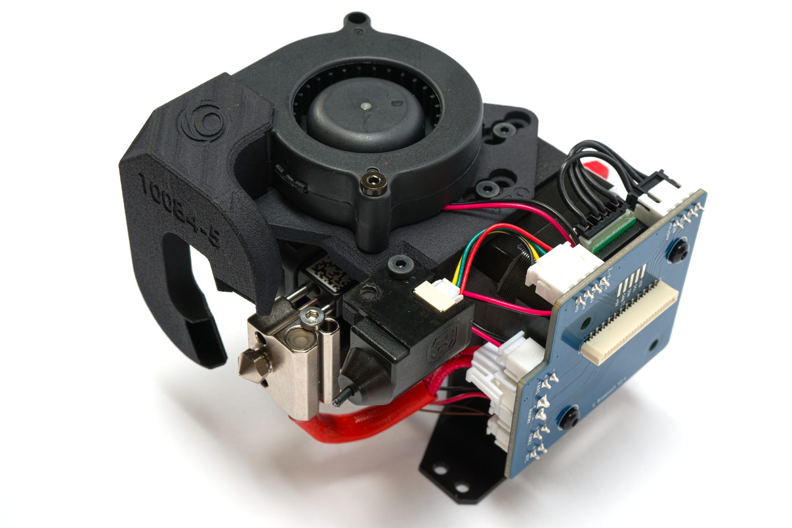
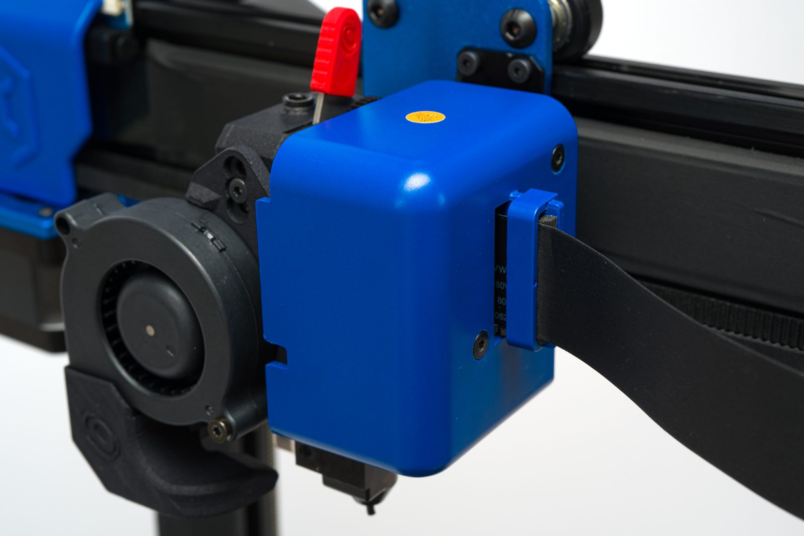
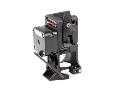
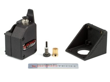
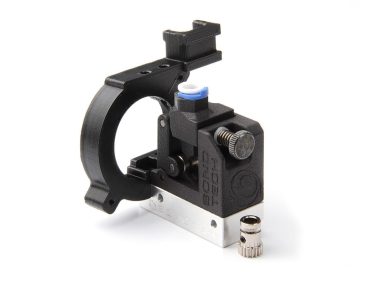
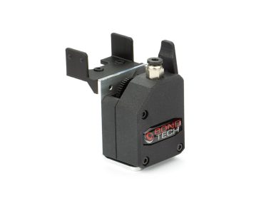
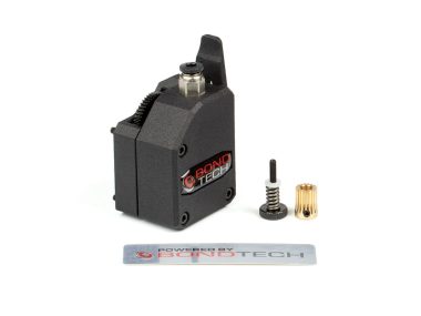
This Upgrade Kit includes an LGX extruder, a Mosquito hotend and a custom Aluminum mount bracket for added rigidity.
Bondtech recommends this set for maker/professional users and for moderate to high-intensity use.
Slice Engineering describes the Mosquito hotend as a radical design featuring a protective roll cage around the most thermally efficient heat break (85%!) available on the market, allowing for cold, one-handed nozzle changes.
Price:
Original price was: $373.75.$305.00Current price is: $305.00.
Available on backorder
Select Currency
Select Country
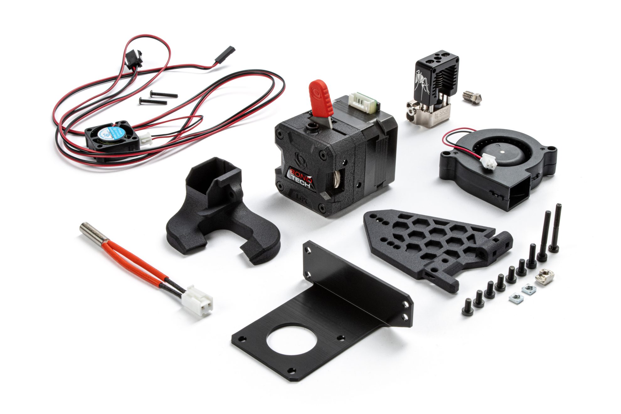
Product Includes:
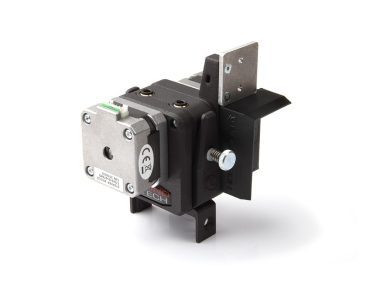
- 1x LGX Large Gears eXtruder
- 1x LGX Accessories For Sidewinder X1, X2, and Genius
- 1x Slice Engineering Mosquito hotend
- 1x Bondtech 24v 50W heater
- 1x Mosquito 24v fan
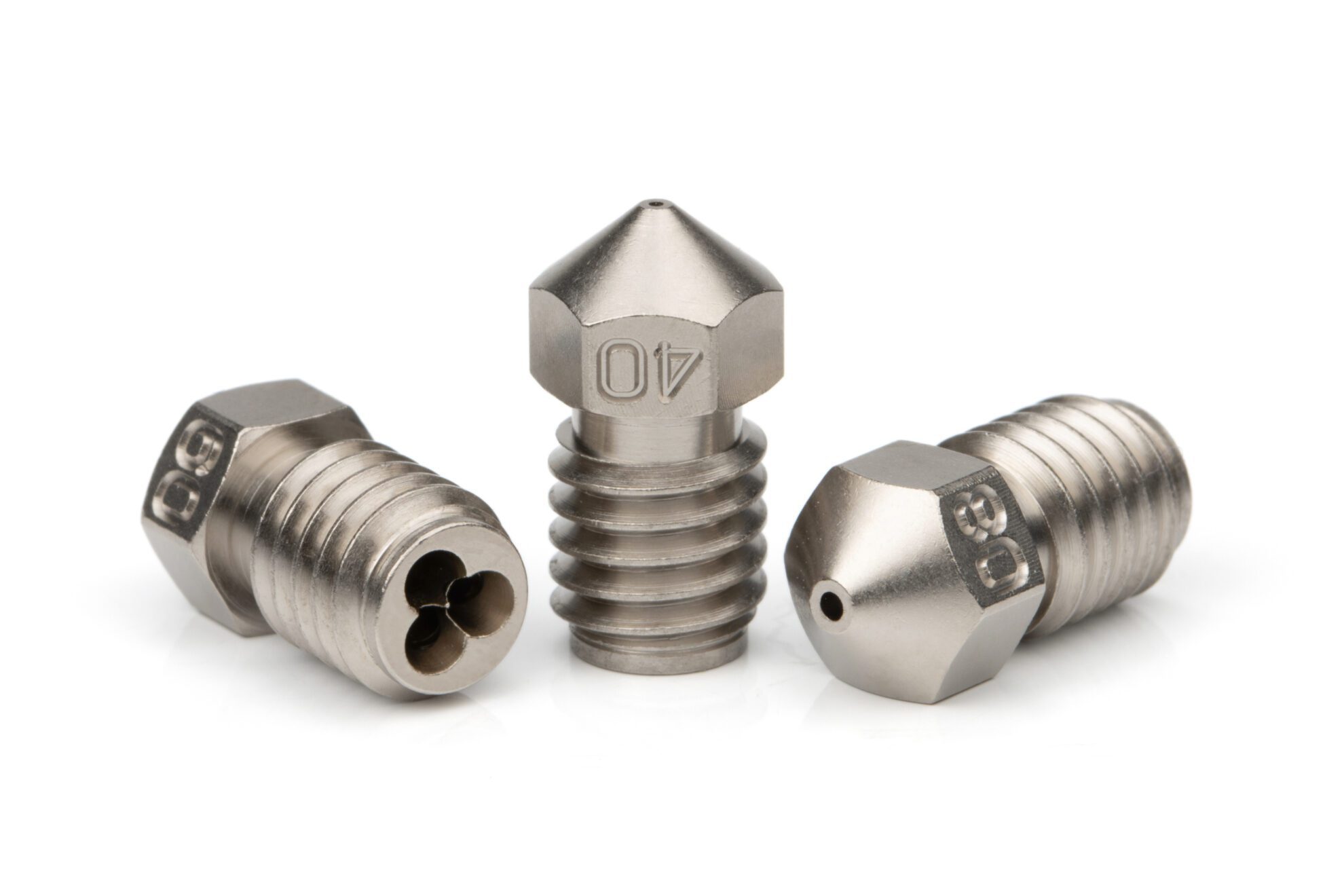
- 1x Bondtech CHT 0.4mm Coated brass nozzle
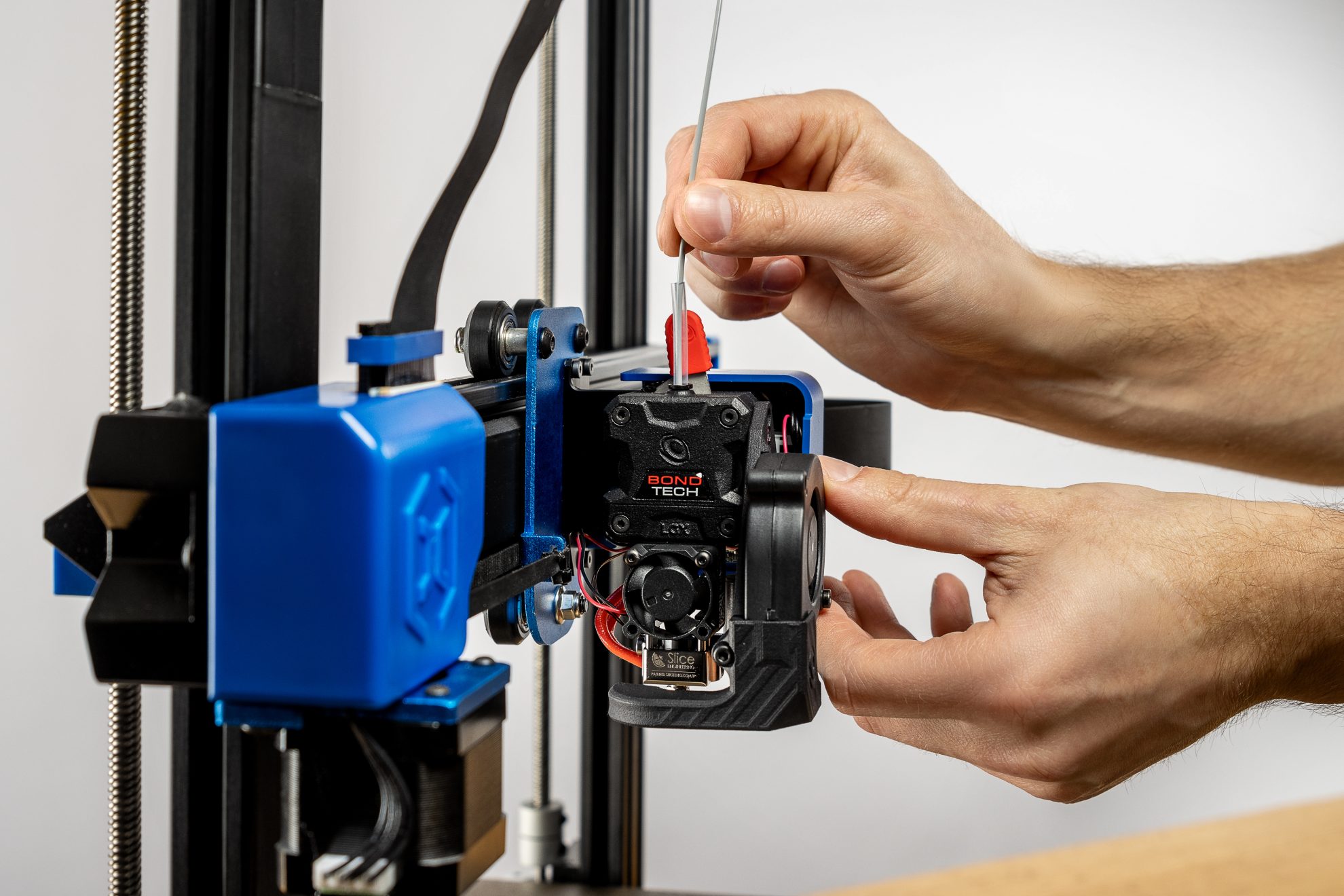
Direct Drive Upgrade
LGX based upgrade kit is an easy to install replacement of the stock direct drive extruder.
Leading Grip Power
The LGX is the Bondtech extruder with the highest filament grip due to its new large drive wheels that put more teeth engaging the filament.
Enjoy Bondtech’s Evolved Dual Drive Technology
Start using our premium extruder with our new Dual Drive Technology based on larger drive gears, one only of the 7 new features Bondtech lately implemented on an extruder.
7 new features on a Bondtech eXtruder:
- Larger drive wheels, for increased filament grip;
- Filament pre-tension lever, for repeated results;
- Multi-function interface socket, for tool or application quick swap;
- Drive wheels’ maintenance windows, for easy cleaning;
- Compact, light & symmetric design, for increased performance and compatibility;
- Multiple mounting hole patterns, for easy and flexible setup;
- A small step for a greener Future, craft boxes without bleaching & no coating.
You can read more about the new features by clicking here.
3D Printed Housing using PA12
The housing parts are professionally printed with nylon for maximum strength and precision and higher temperature resistance.
| Freight Weight | 618 g |
|---|---|
| Dimensions | 21.5 × 8 × 11 cm |
Technical Specification
LGX extruder
- e-steps value : 400 using 16 microsteps; 800 using 32 microsteps.
- Drive wheels : hardened steel;
- Materials compatibility : abrasive; rigid; semi-flexible; flexible; and soft.
- Mounting holes : M3
- Mounting patterns : bottom anterior (2 points); left (2 points), right (2 points), front (4 points), back (4 points)
- Holes on the sides of the LGX™ : 5 mm depth
- Holes on the bottom of the LGX™ : 12 mm depth
- Max tightening torque on the extruder screws is 0.3 Nm
Using a plate between the extruder and the stepper motor
- Max thickness : 2.6 mm
- Optimal Thickness : between 0.3 and 2.3 mm;
Optimal Thickness allows full teeth engagement between the motor gear and the main double gear.
For Klipper users
rotation_distance = full_steps_per_rotation * microsteps / steps_per_mmrotation_distance = 200 * 16 / 400
rotation_distance = 8The above calculation assumes the following parameters:
- stepper motor is a 1.8 degrees motor hence 200 as full steps per rotation;
- microsteps are set to 16;
- e-steps value recommended for the LGX is 400.
Although we recommend to use the rotation_distance instead of the gear_ratio, we inform the LGX gearing ratio is 44:14, 37:17.
- To use the LGX directly attached to the hotends listed below,
PTFE tube lengths should be:- Old Mosquito/Mosquito Magnum : 10 mm
- New Mosquito/Mosquito Magnum : 11 mm
- Copperhead screw mount : 30 mm
- PTFE tube should be cut straight on both ends.
- Slight chamfer inside is recommended, but not mandatory.
- retraction speed : 35 mm/s
- retraction distance (bowden) : ~5 mm (0.4 + tube length[mm] x 0.015)
- retraction distance (direct drive) for rigid materials : 0.4 mm
- retraction distance (direct drive) for soft materials : 3 mm
- Max Environment operating temperature : 70°C
- Max stepper motor running temperature (using LGX) : 80℃
- Recommended stepper motor Current (using LGX) : 0.45 to 0.60 A (RMS)
- LGX™ DD net weight : 218.6 g
- LGX™ B net weight : 224 g
- Package measurements : 80x103x73 mm
- Package weight : 269 g
- Download the LGX Technical Drawings here.
Custom Stepper Motor for Bondtech LGX™
- Requires cable with PHR-6 connector
- 2 phases
- DC 3.1 V
- Max 0.7A / phase
To use the LGX®, run the stepper motor with currents between ~0.45 and ~0.65A:
Be vigilant regarding the stepper motor surface temperature.
Keep it cool enough to touch. Lower Vref otherwise. - Class H motor, rated up to 180°C
- Max recommended environment : 70°C
- Max temperature at this environment temperature can go up to 130°C on account of the self heating.
- Download the stepper motor Technical Data Sheet here.
How to change the Current using Vref
It is very hard to read the current being fed to stepper motors. To determine that current we rely on the Vref value. The Vref value is a voltage reference measured in VDC that can be read using a multimeter. It helps us setting the current output of the stepper motor driver.
Different 3D printer mainboards use different stepper motor drivers. Each type of stepper motor drivers has its own formula to calculate the required Vref to get a specific current. Here are some examples:
- TMC stepper drivers.
The formula for these drivers is Vref = ( I * 2.5 ) / Imax
Where I is the target current value measured in A; and Imax is 1.77 on regular mode and 1.2 on SilentStepSticks mode. - Pololu A4998.
The formula for these drivers is Vref = I * 8 * R
Where I is the target current value measured in A; and R is the Sense Resistor value, that depends on what board are you using. Melzis use 0.1. The Creality Silent boards use 0.15, ...
SETUP GUIDE
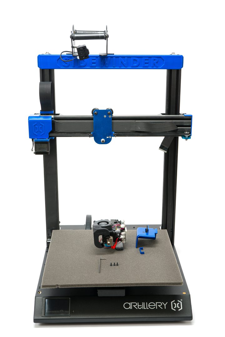
Setting Up the LGX extruder on the Artillery Sidewinder X2
The guide below shows how to install the LGX on the Artillery Sidewinder X2. The same process can be implemented on the Sidewinder X1 and Genius.
The whole process is divided into 3 stages. Click each tab's arrow below to reveal the steps on each stage. This guide assumes you know how to operate the Artillery Sidewinder. If you don't, please refer to the manufacturer's documentation.
You may click the guide's pictures to view bigger resolution versions.
Click the Step ?/4 titles to see the photos and descriptions.
On the Artillery Sidewinder X1
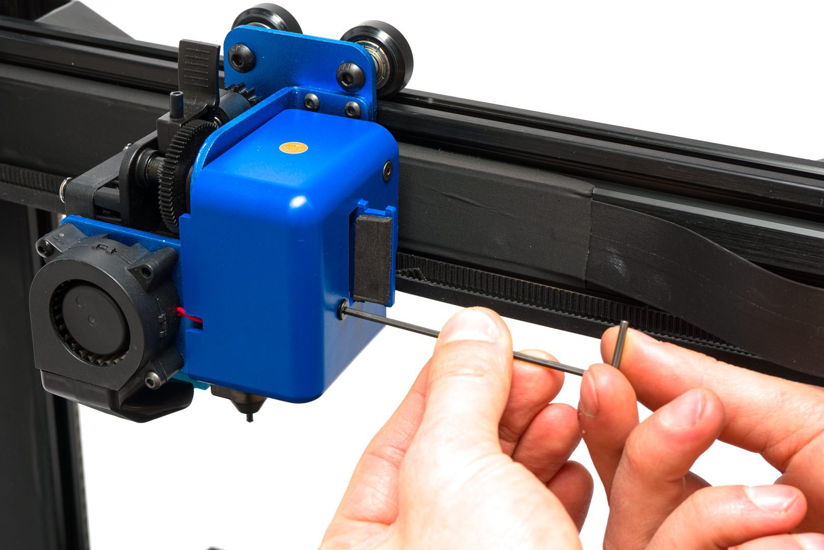
Using the hex key can be helpful to push out the heater.
BE VERY CAREFUL AND DO NOT PULL IN THE CORDS SINCE THEY CAN BREAK EASILY.
On the Artillery Sidewinder X2
Step 1. Stripping down the printer
Use the list and video below to strip down the Artillery Sidewinder X1. The process is very close to stripping down the X1 or Genius.
- Unload filament and let hotend cool down.
- Turn off printer.
- Remove ribbon cable.
- Remove Breakout board
- Remove LED chip
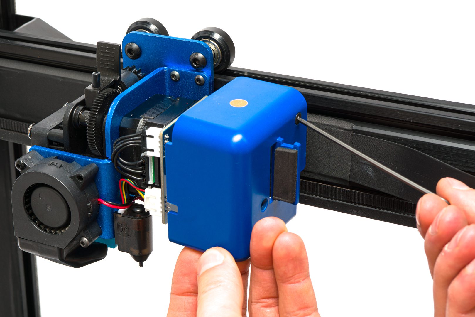
- Detach printhead from X-carriage.
- Detach breakout board.
- Remove spacer plate
- Unplug connectors from breakout board.
- Detach bed levelling sensor.
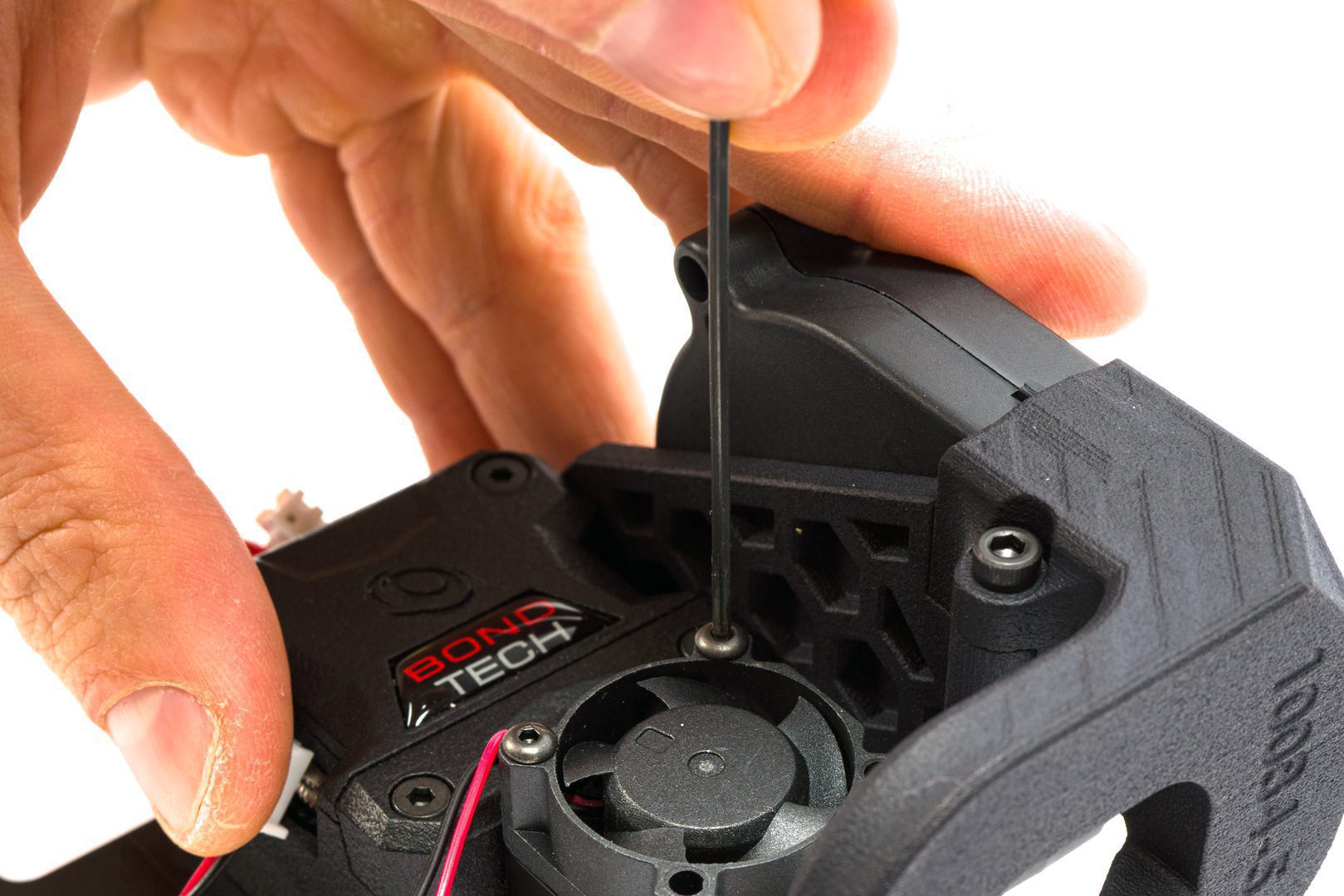
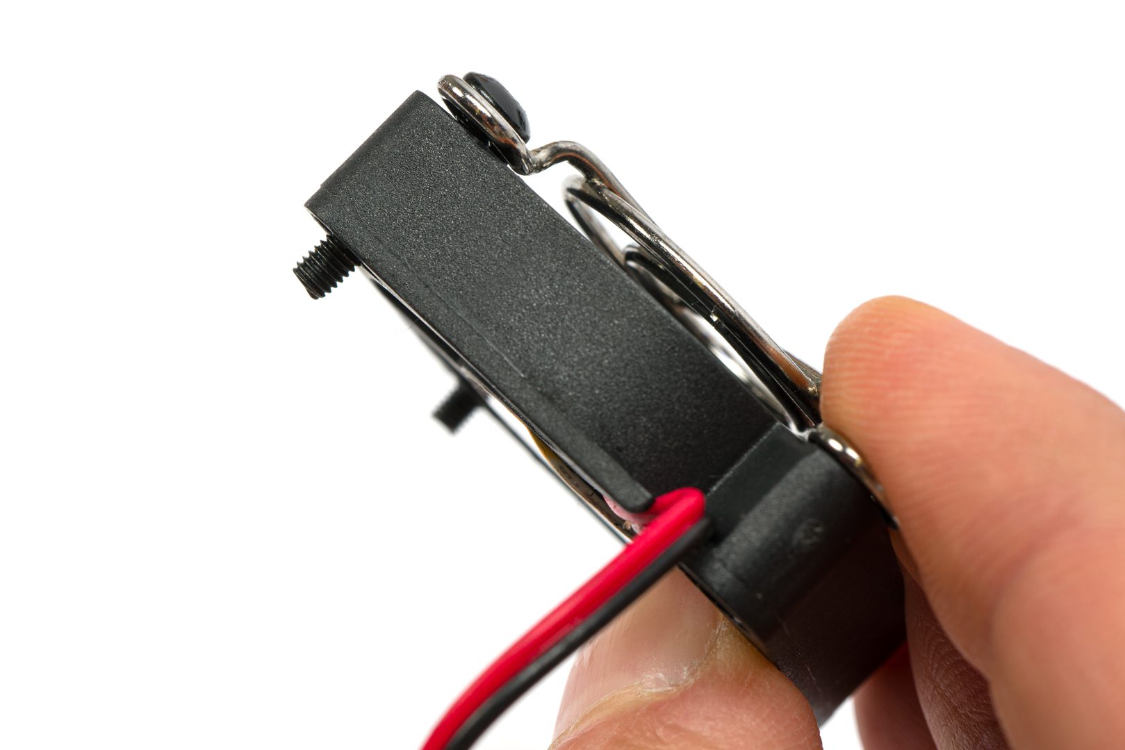
- Detach 4010 hotend cooling fan.
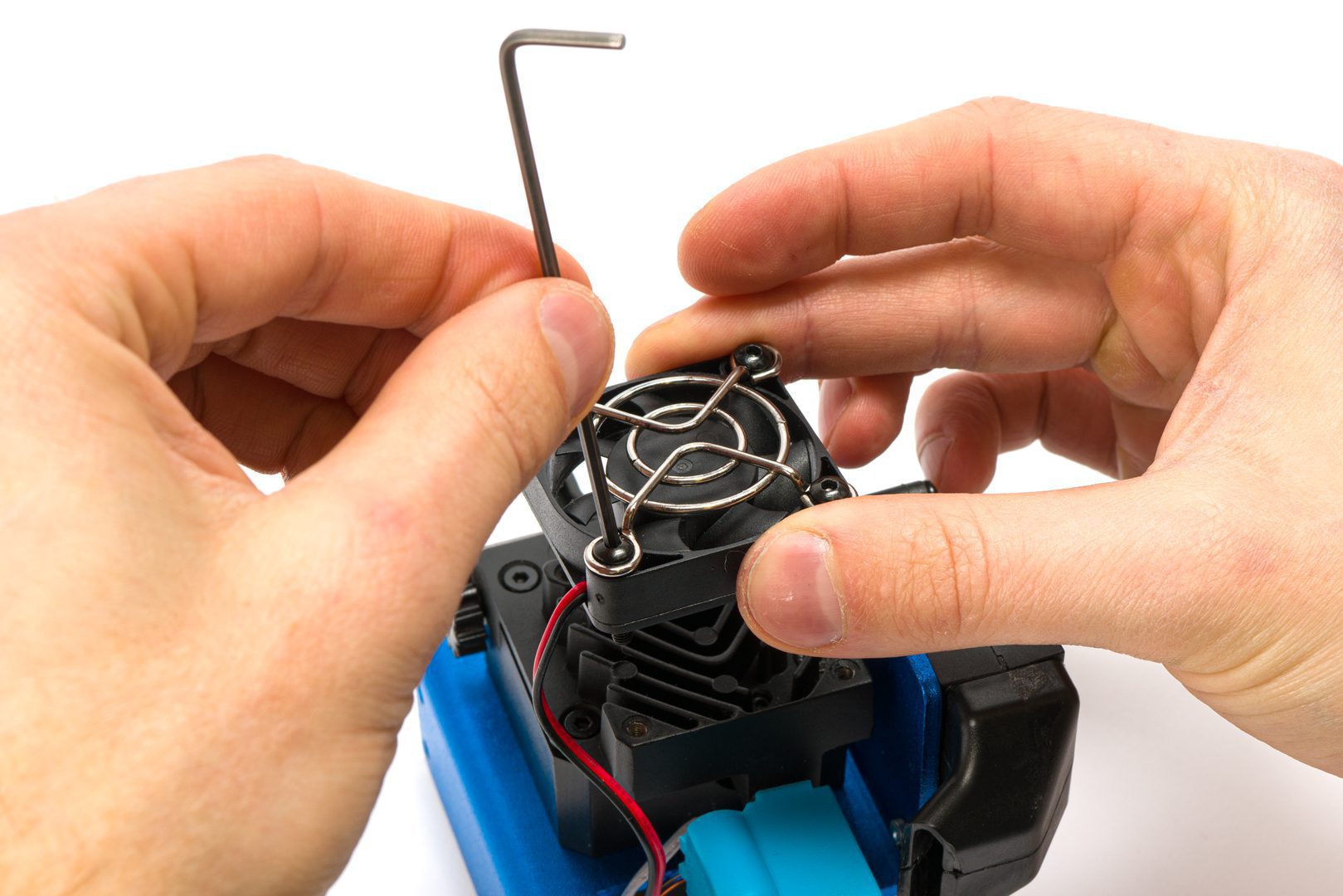
- Remove hotend from heat sink.
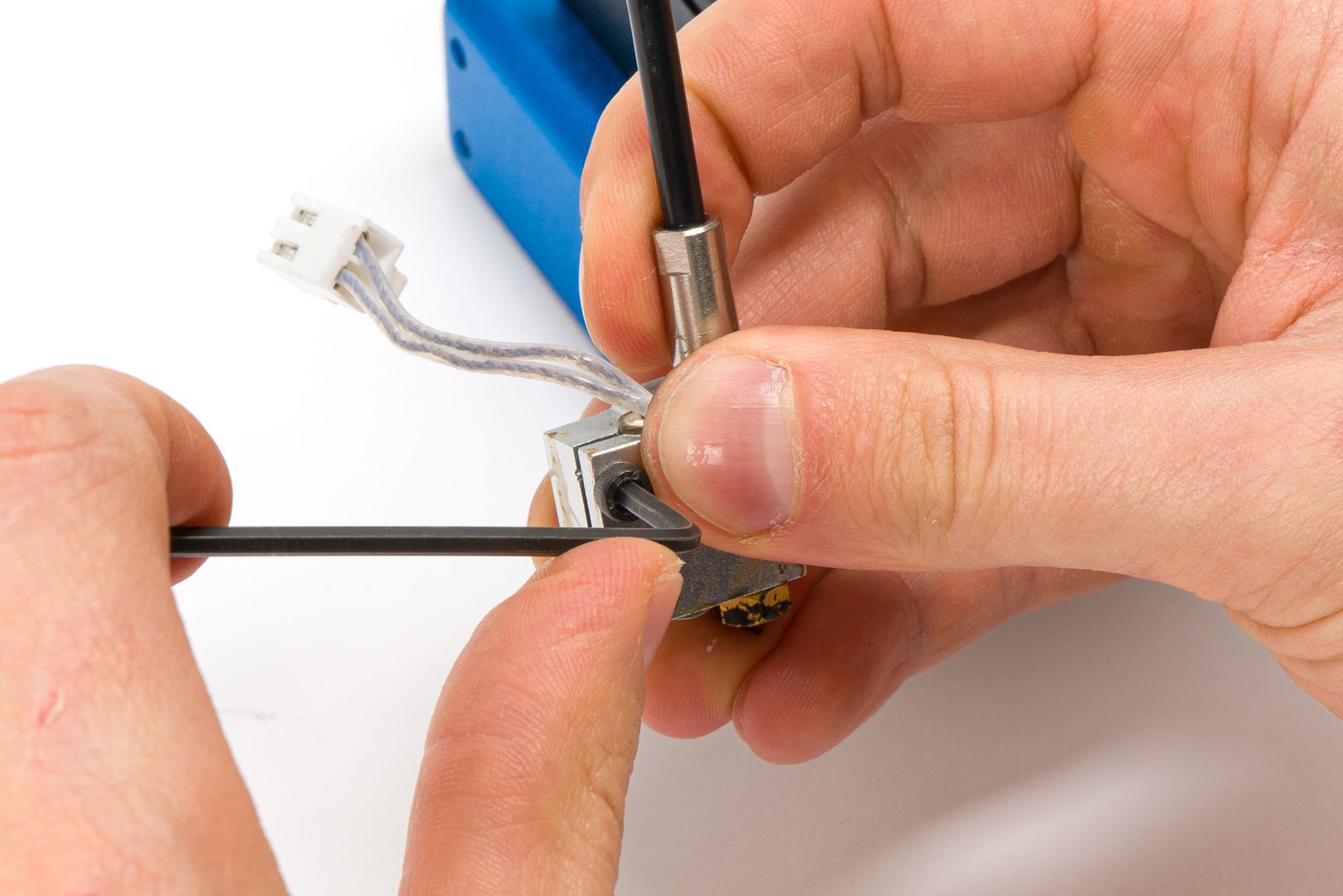
- Remove heater and thermistor from hotblock.
Using the hex key can be helpful to push out the heater.
BE VERY CAREFUL AND DO NOT PULL IN THE CORDS SINCE THEY CAN BREAK EASILY.
Unload filament. Let the hotend cool down.
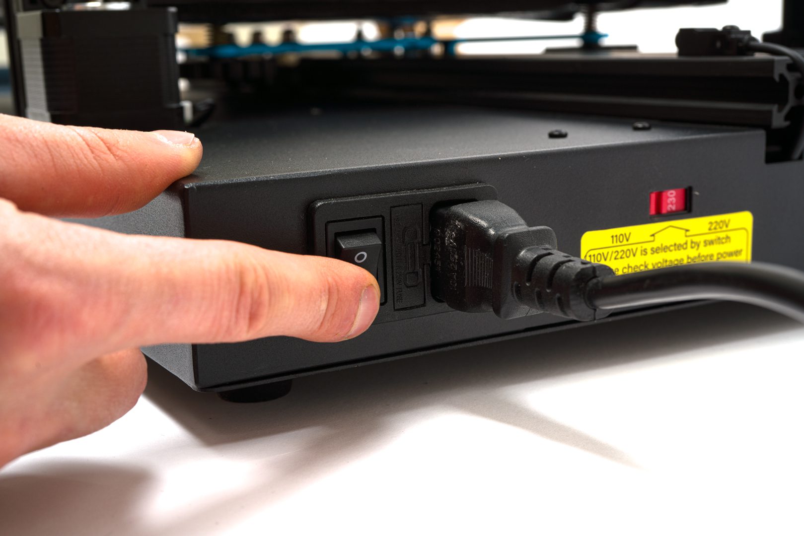
Turn off the printer.
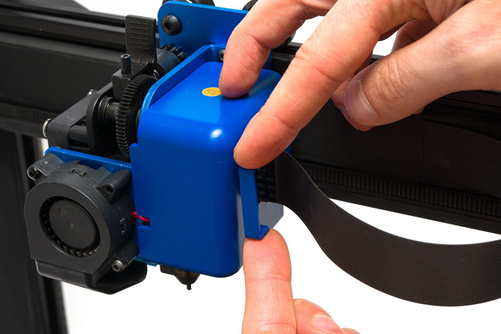
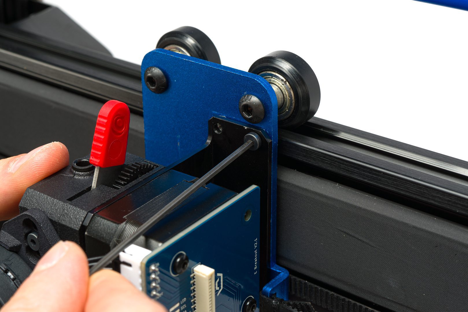
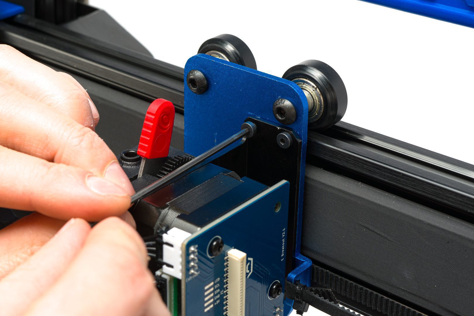
Remove ribbon cable lock
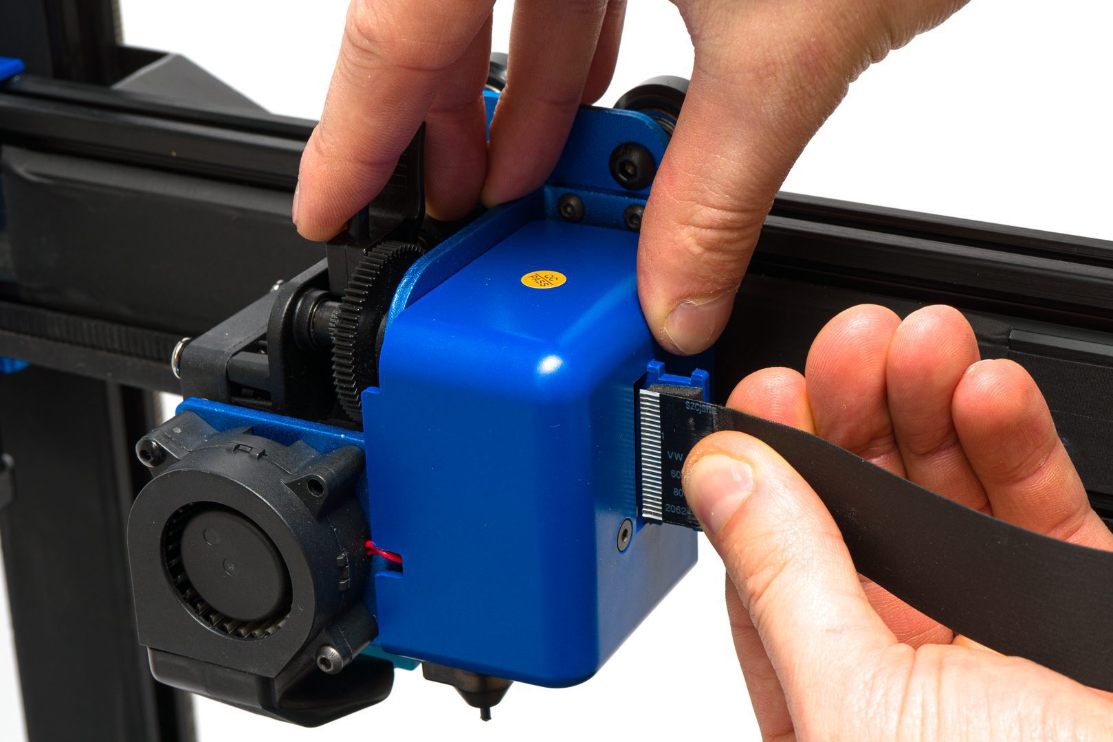
Remove ribbon cable
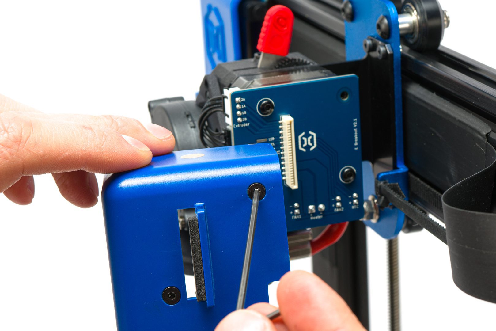
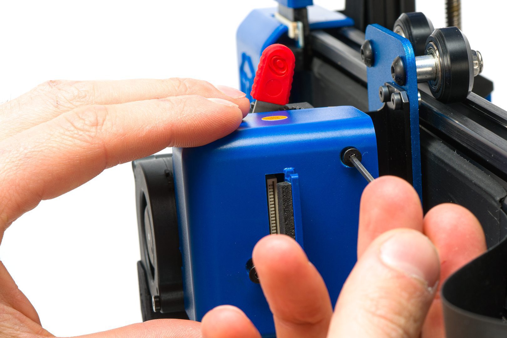
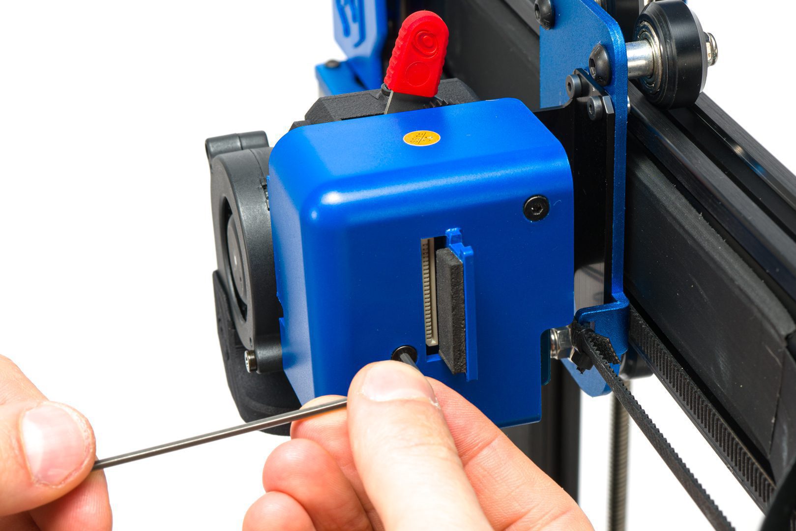
Remove Breakout board cover
Remove Breakout board cover
If you have a loose LED chip that can be removed, please remove it.

Detach printhead from X-carriage
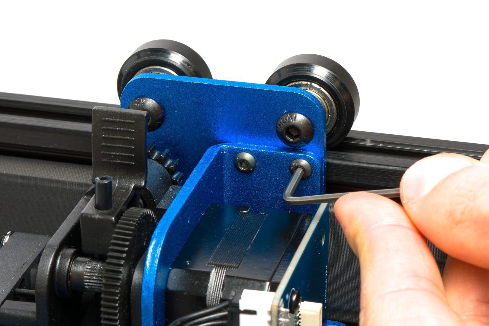
Detach printhead from X-carriage
Detach printhead from X-carriage
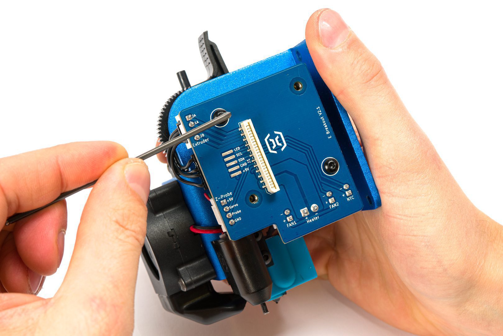
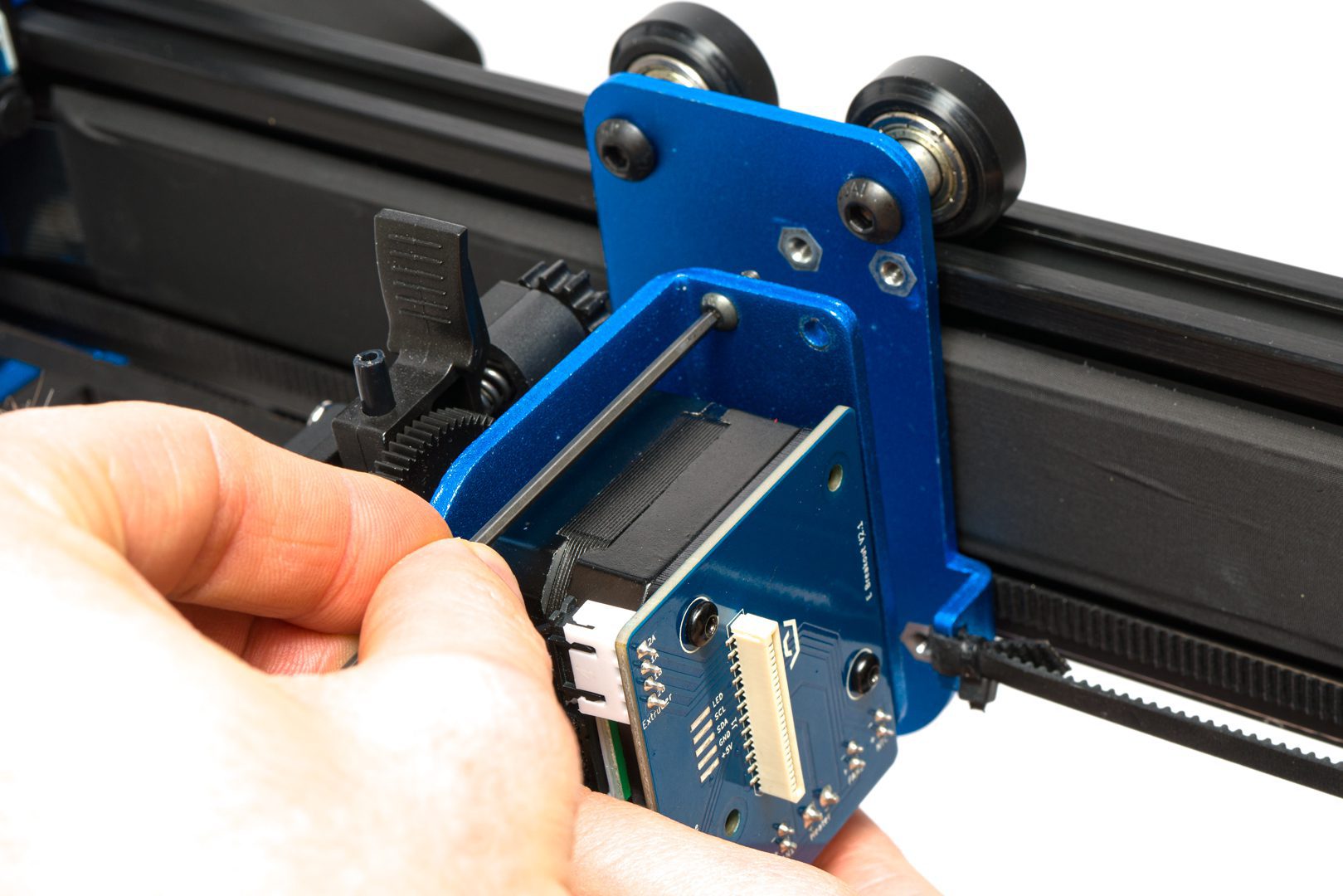
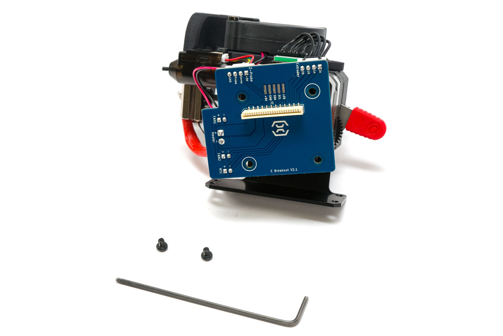
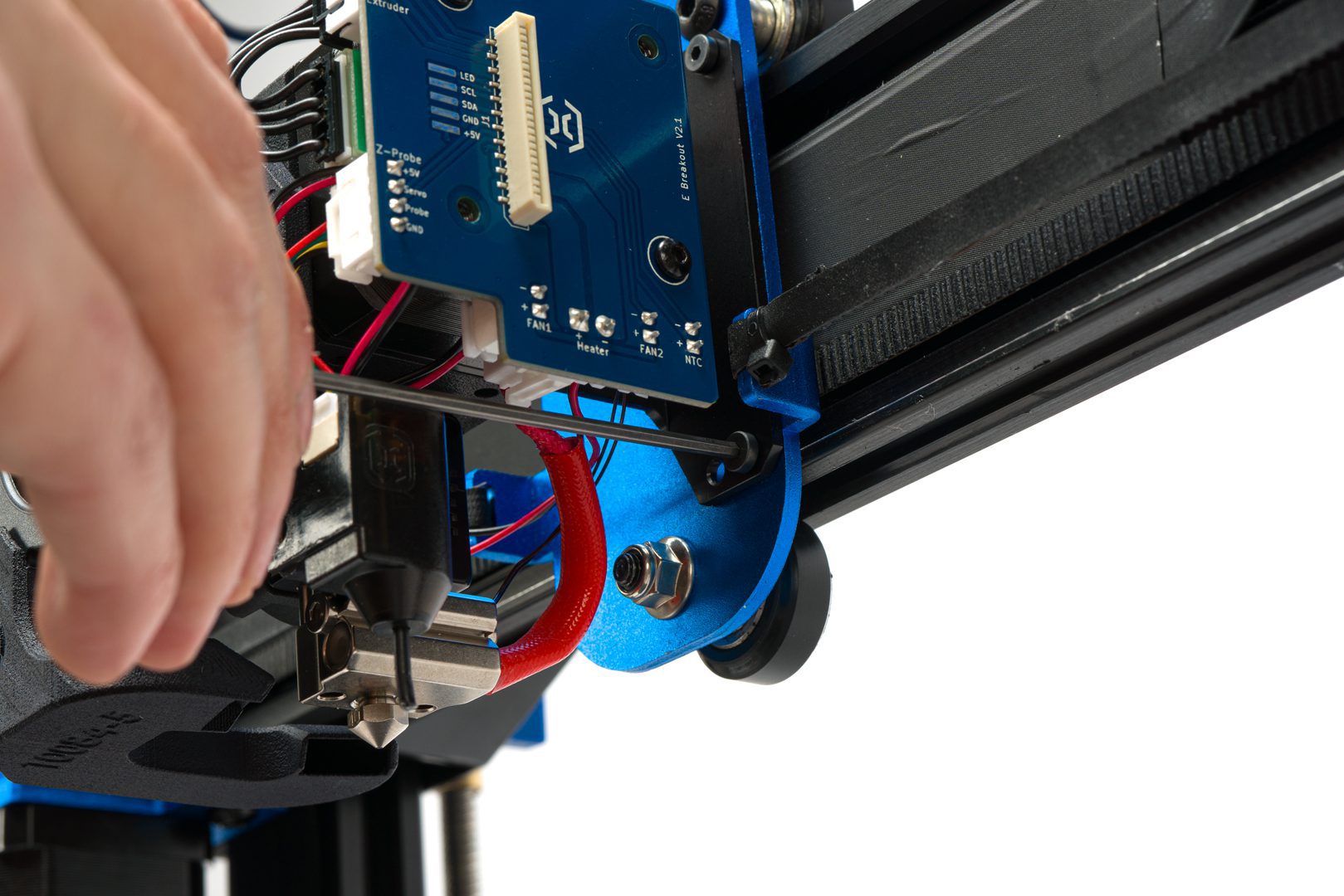
Remove breakout board
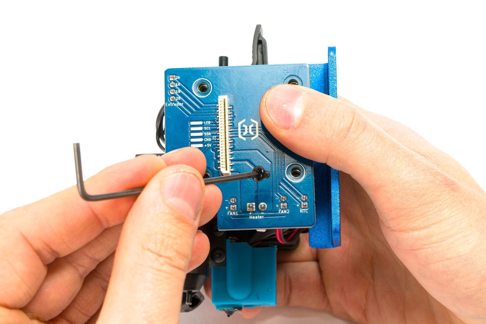
Detach breakout board
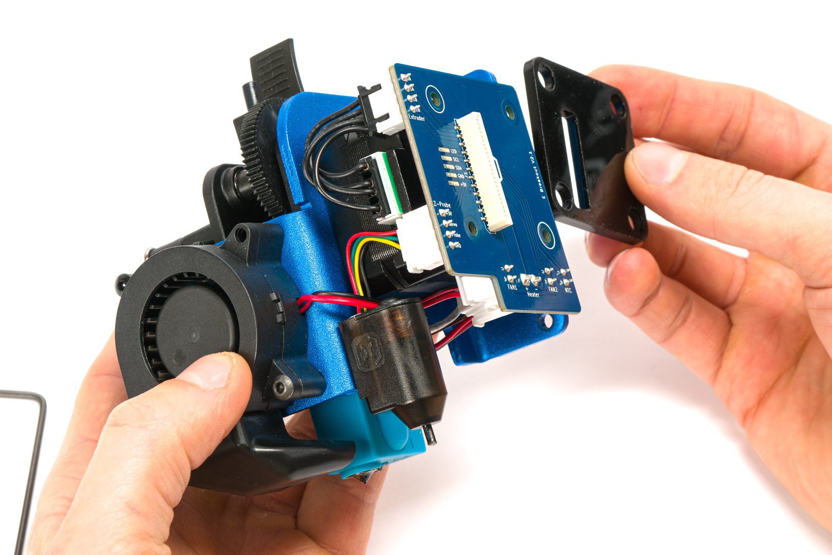
Remove spacer plate
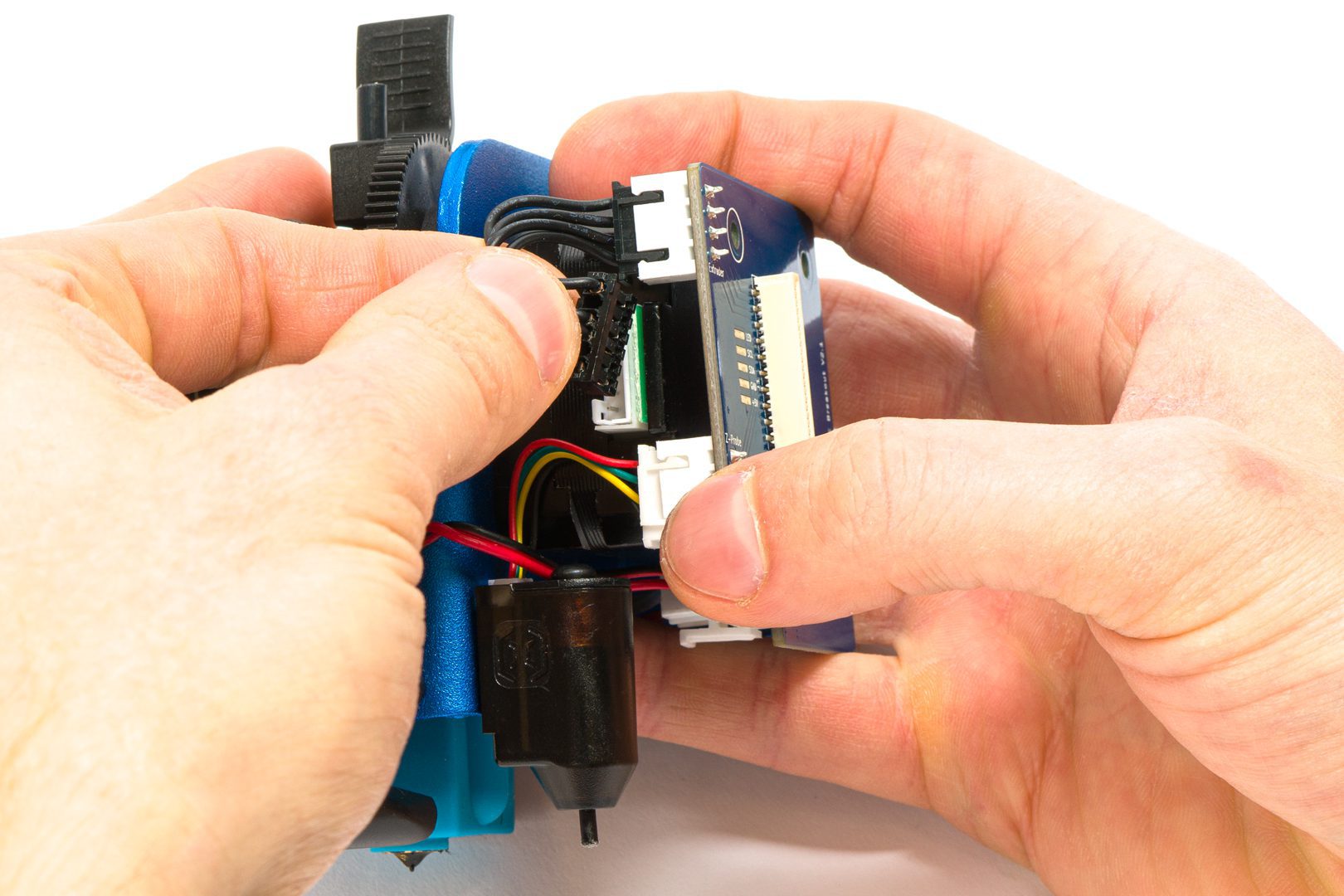
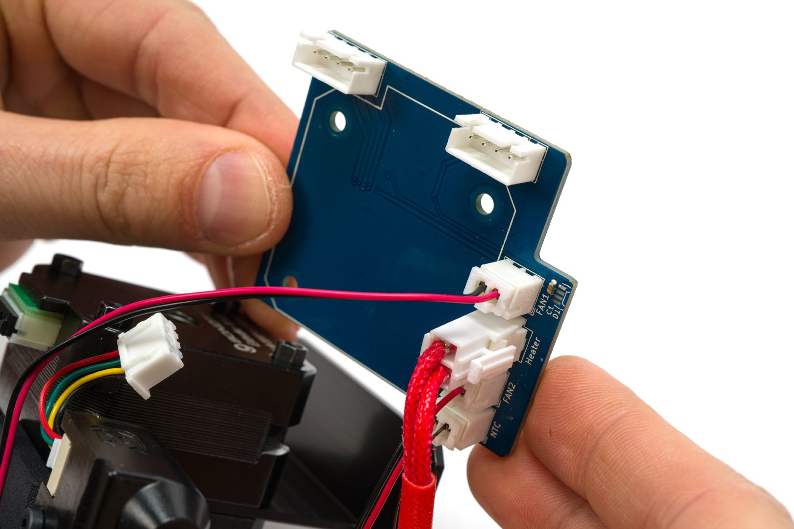
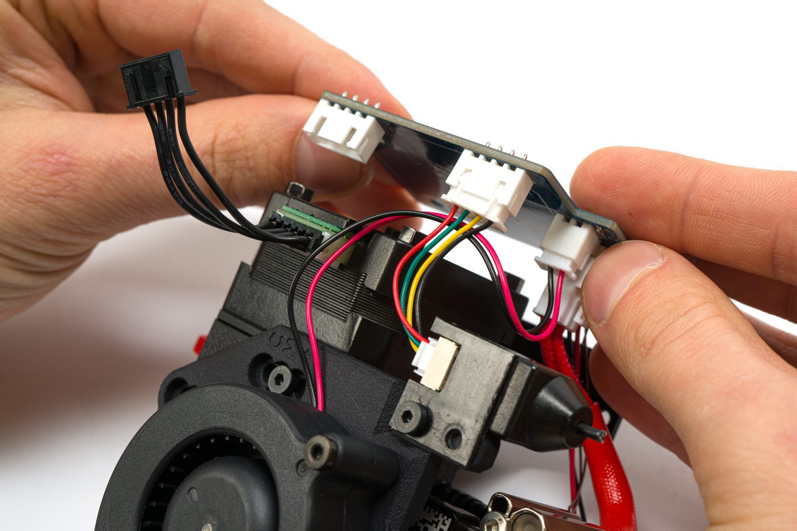
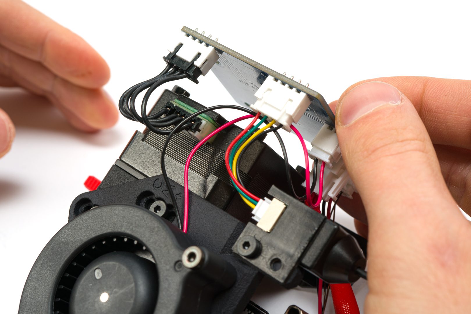
Unplug connectors from breakout board.
Unplug connectors from breakout board.
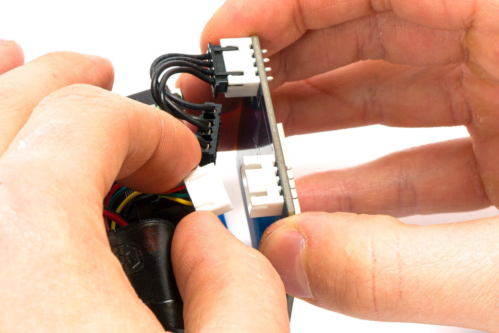
Unplug connectors from breakout board.
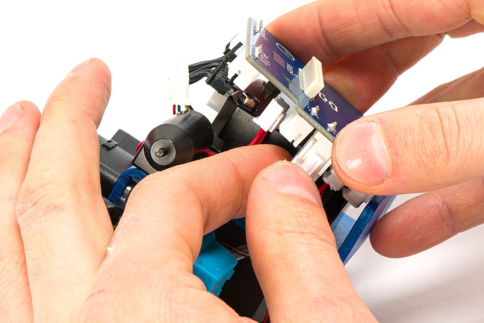
Unplug connectors from breakout board.
Unplug connectors from breakout board.
Unplug connectors from breakout board.
Detach Z sensor.
Detach 4010 cooling fan.
Remove hotend from heatsink.
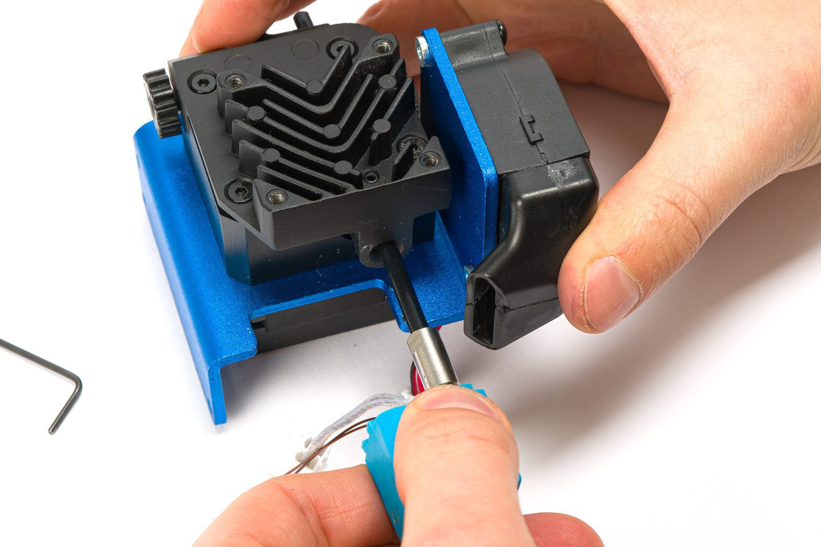
Remove hotend from heatsink.
Remove thermistor from hot block.
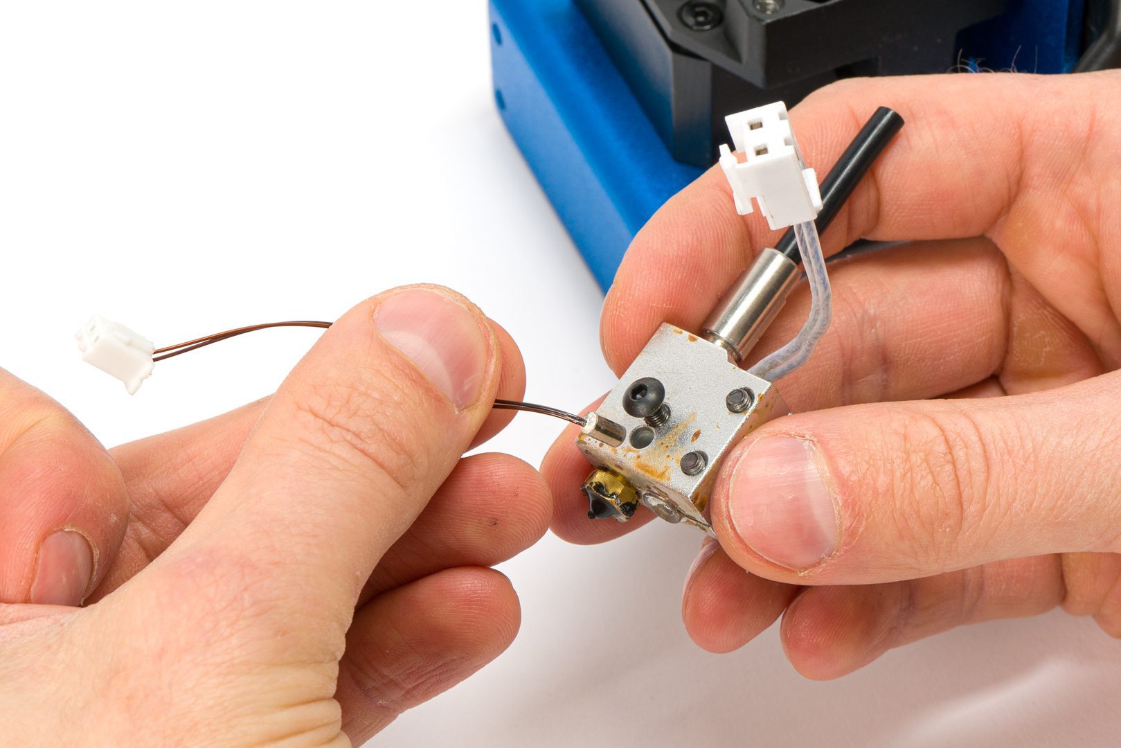
Remove thermistor from hot block.
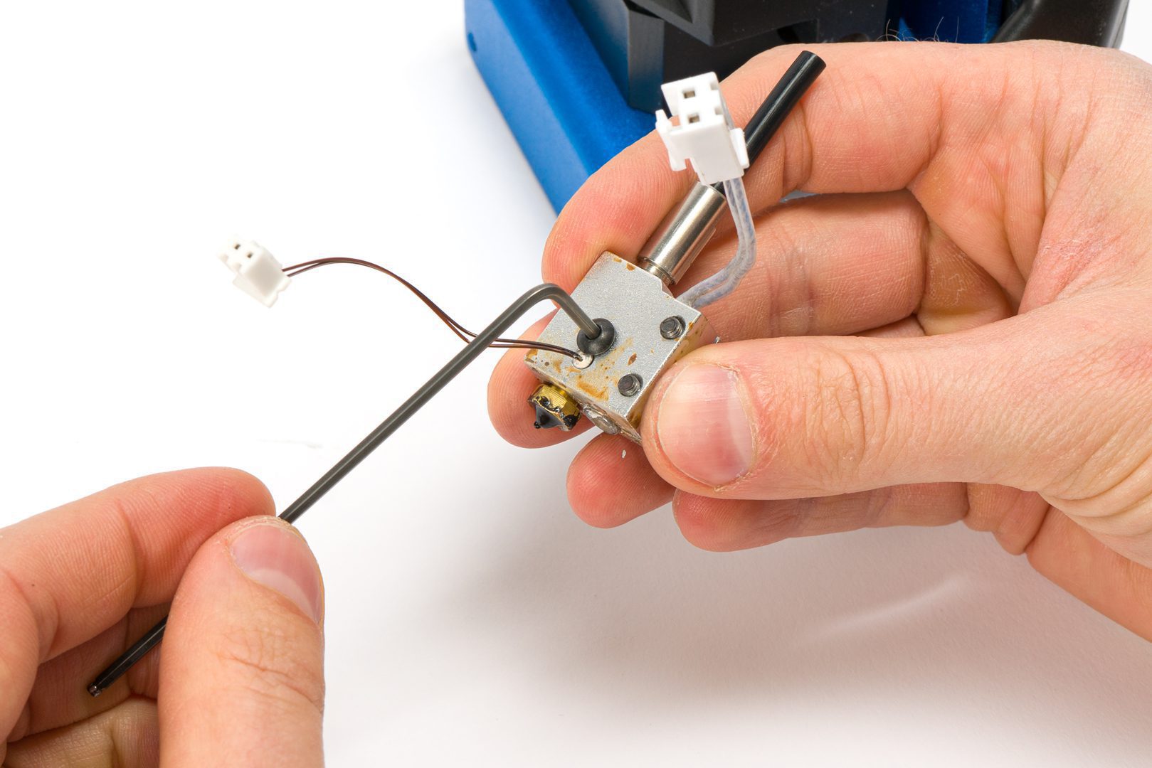
Remove heater from hot block.
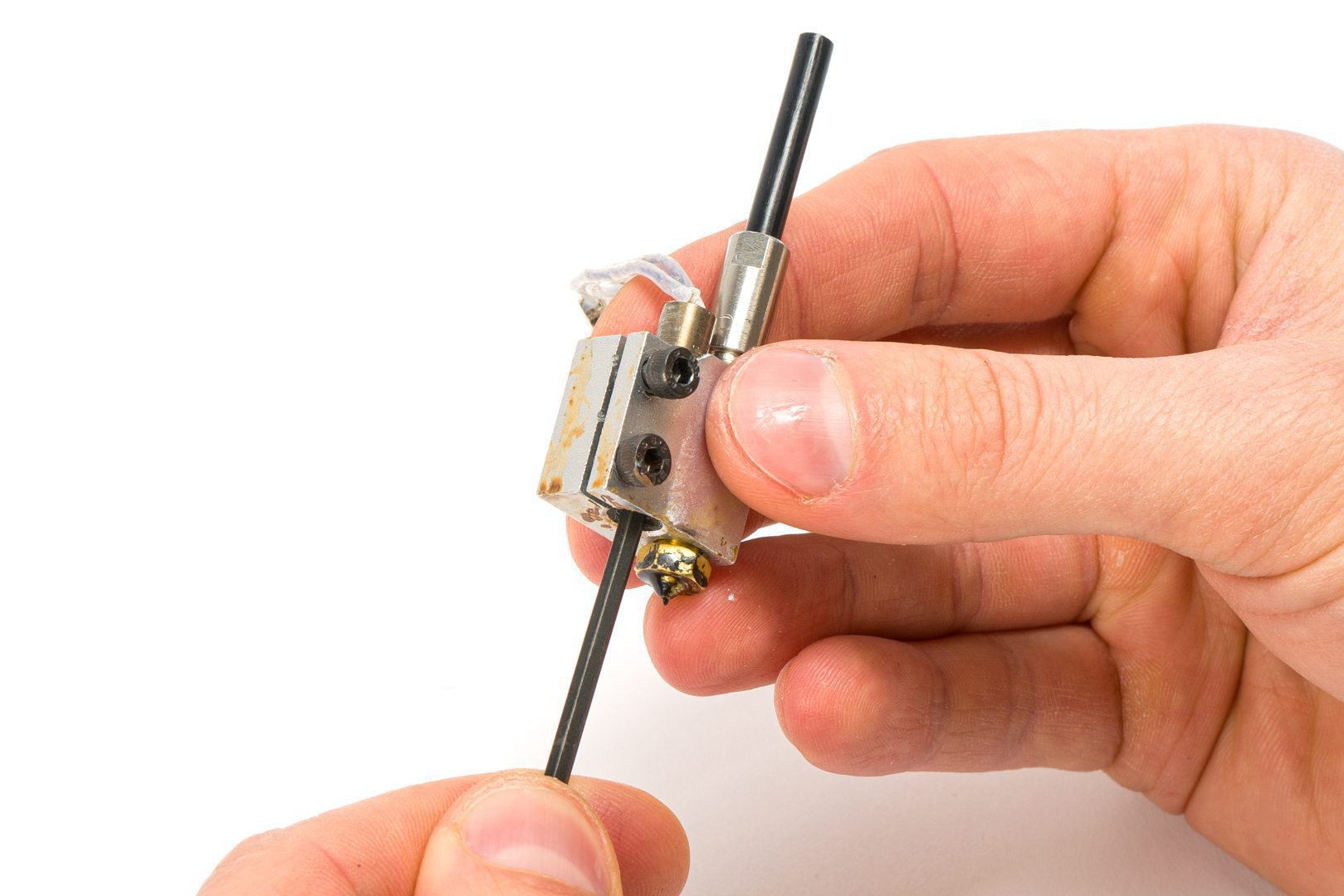
Remove heater from hot block.
BE VERY CAREFUL AND DO NOT PULL IN THE CORDS SINCE THEY CAN BREAK EASILY.
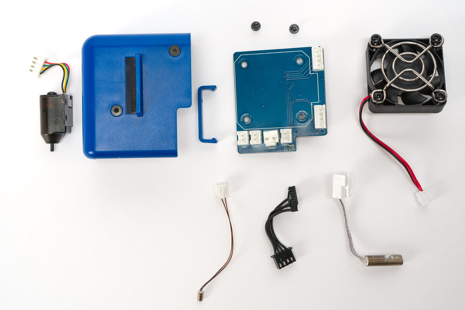
What to re-use and what not
NOT REQUIRED : breakout board spacer; silicone sock , hotend; 4020 part cooling fan; extruder; stepper motor; mounting plate.
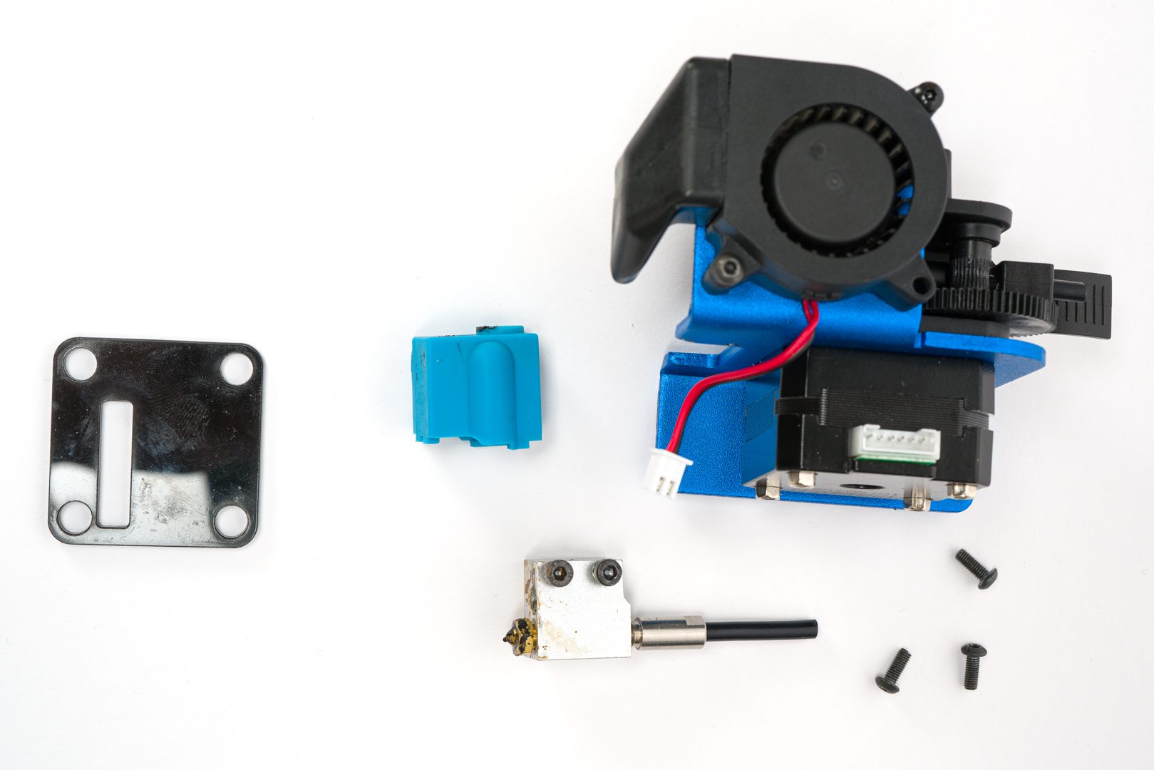
REQUIRED : Z-sensor, breakout board cover; breakout board; 4010 cooling fan; heater; thermistor; stepper motor cable.
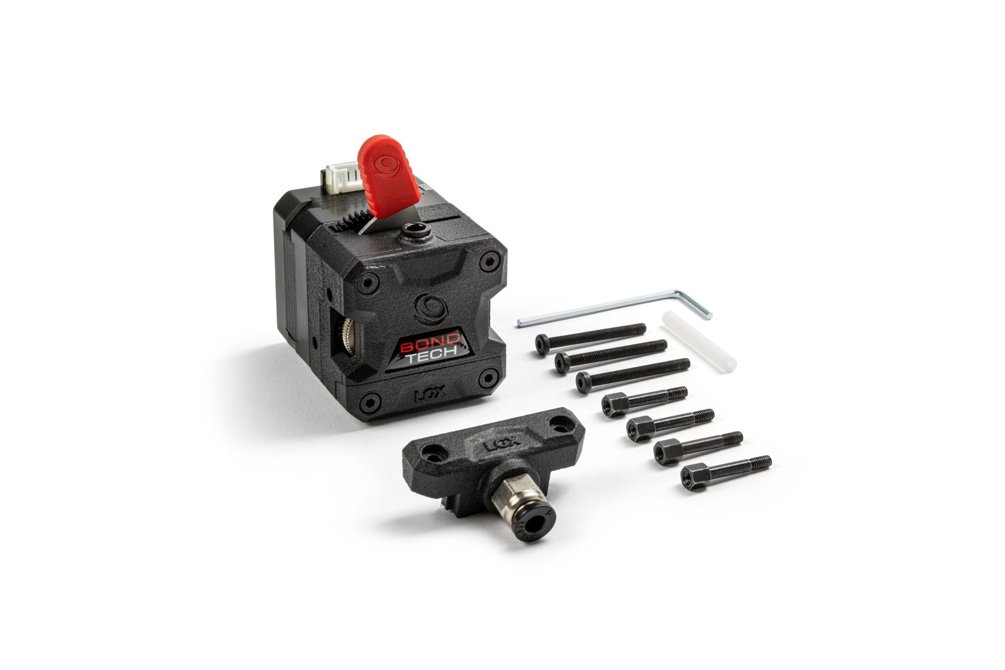
Check if you have all the necessary tools and items for this step
Tools you will need:
- Torque Wrench to tighten the studs;
- Phillips screwdriver;
- 2.0 mm hex key;
LGX accessories you should have:
- 4x M3x18 mm Stud with 5mm Hex with M3x4 thread;
- 1x M3x30 mm Low Head screws;
LGX for Artillery accessories you should have:
- 1x Aluminum Mount;

Step 2.1 Install the LGX studs
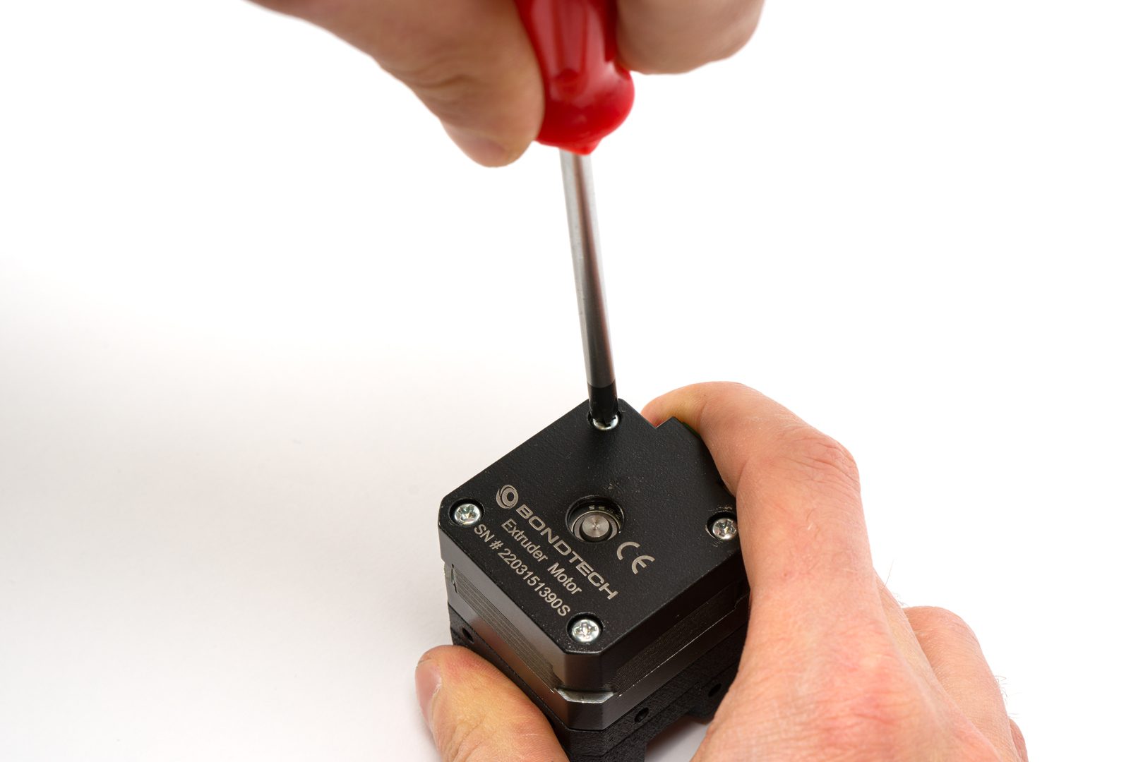
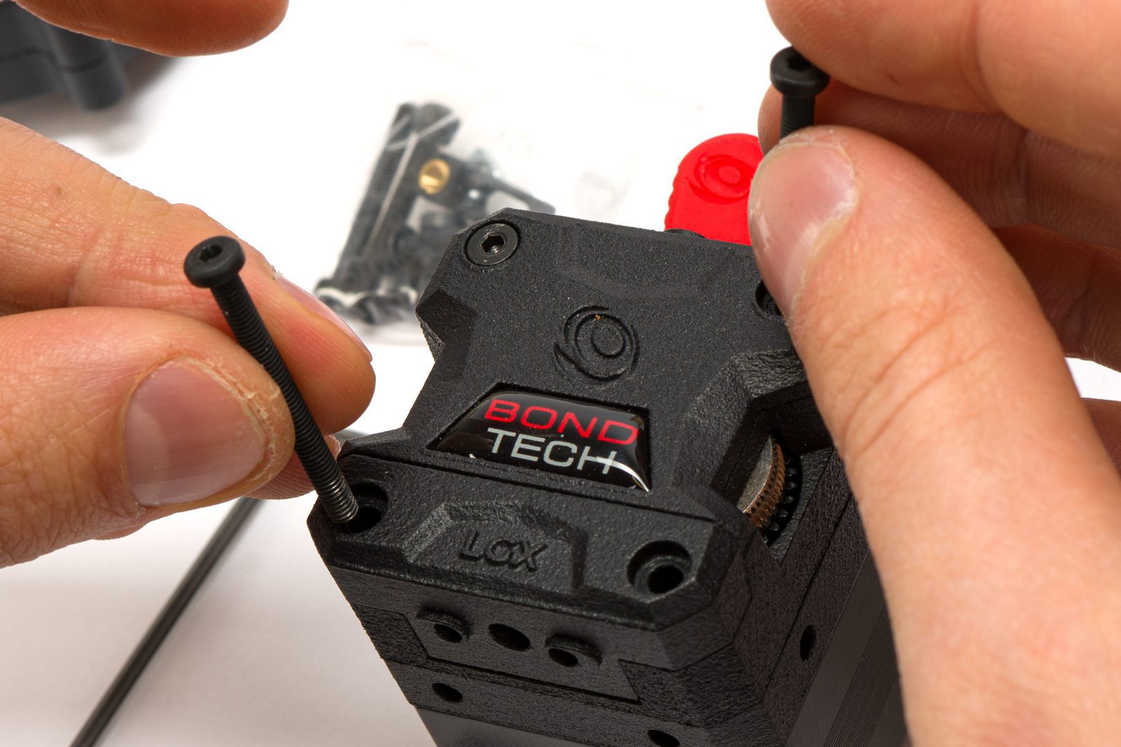
Remove the screws at the back of the stepper motor
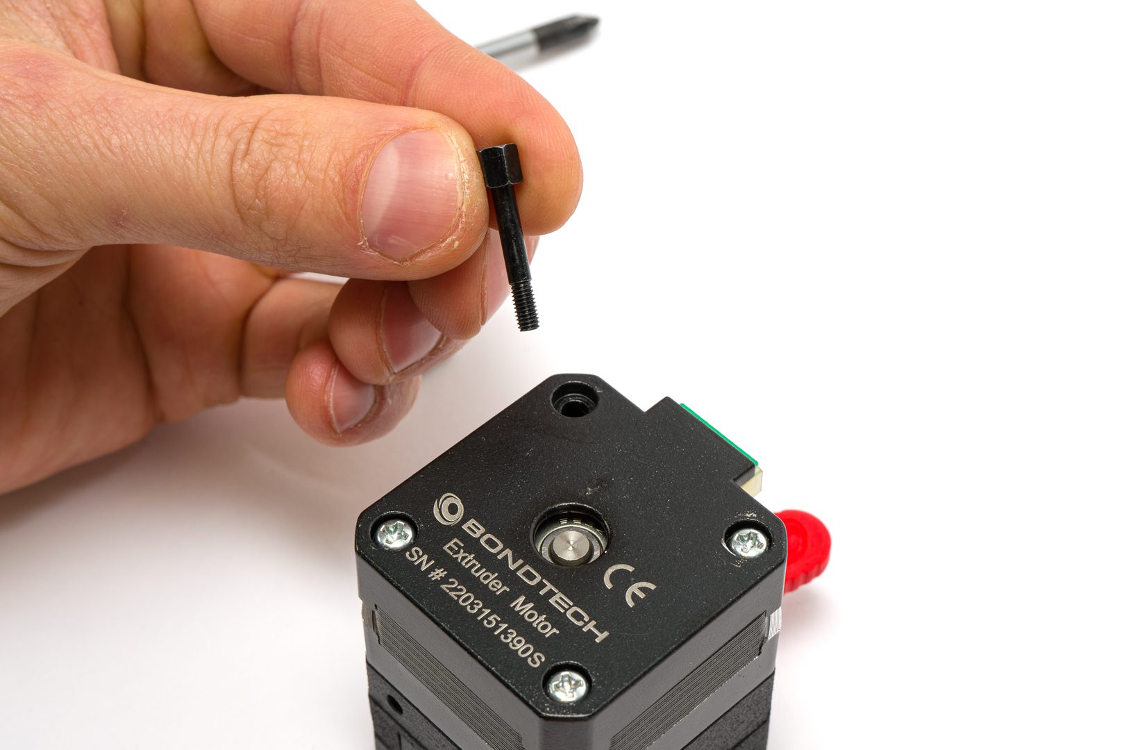
Replace them with the studs supplied
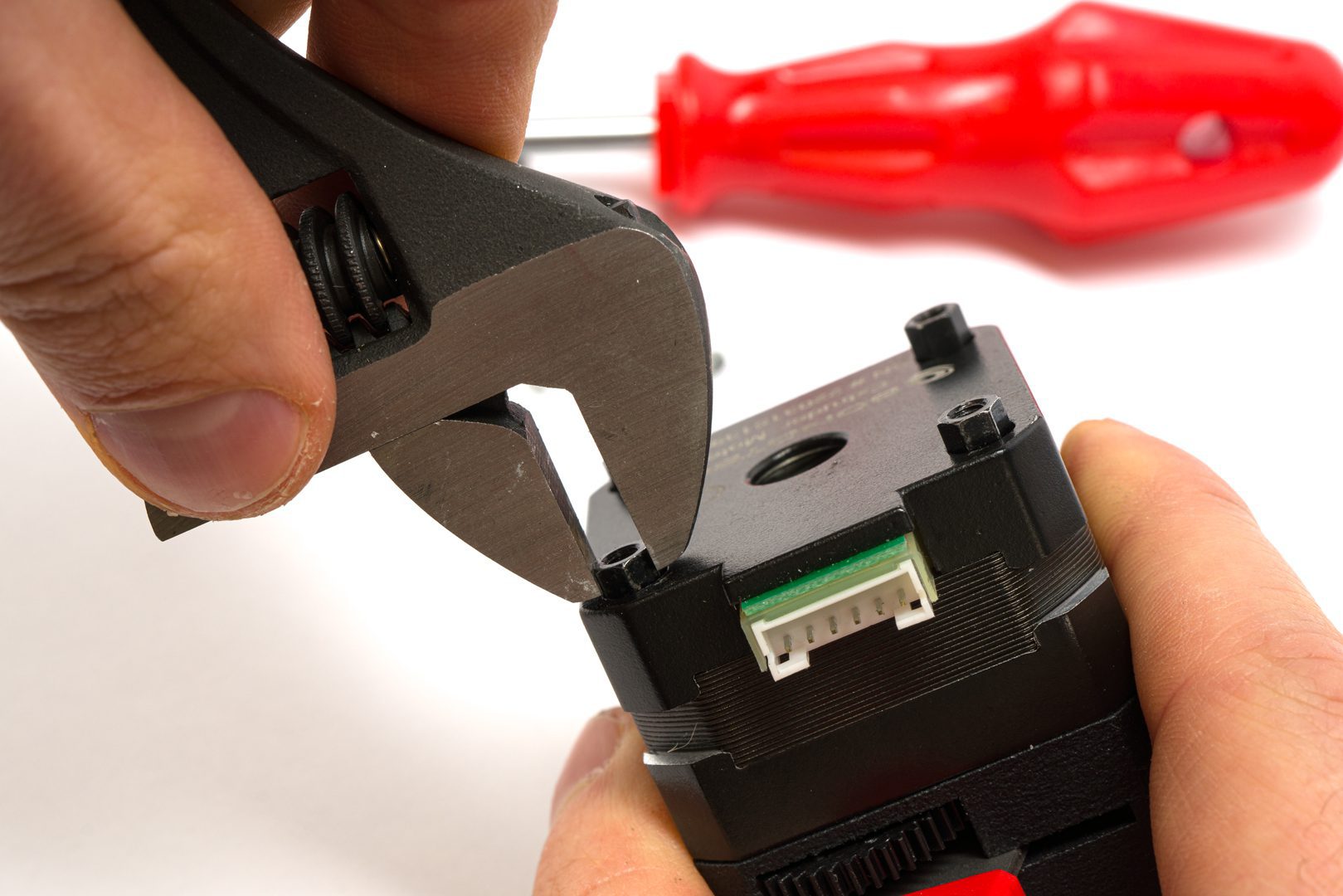
Use the wrench to tighten the studs to the motor
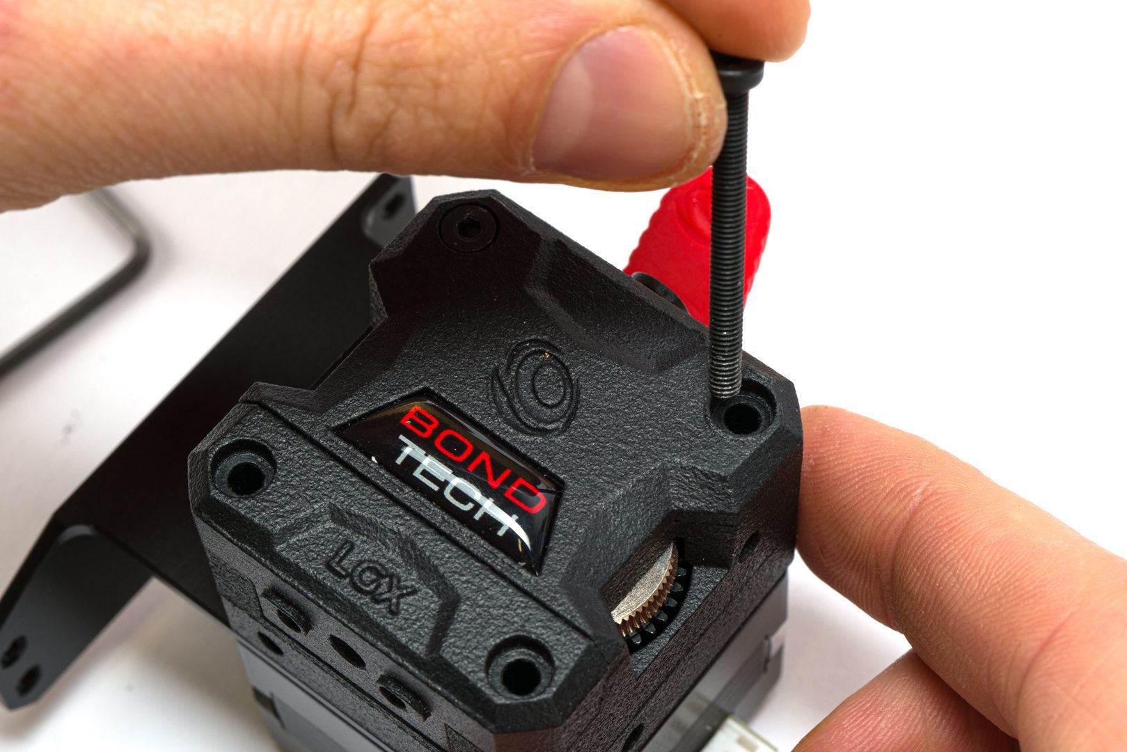
Step 2.2 Separate the LGX from the stepper motor
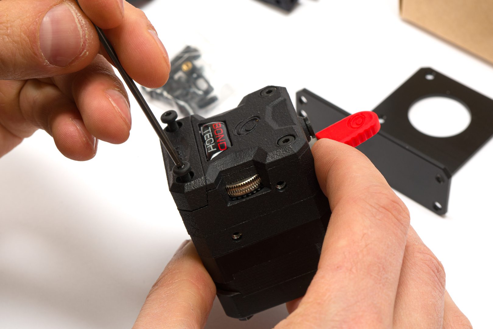
Unscrew the LGX's bottom and top right front screws
Remove the LGX's front screws except the top left
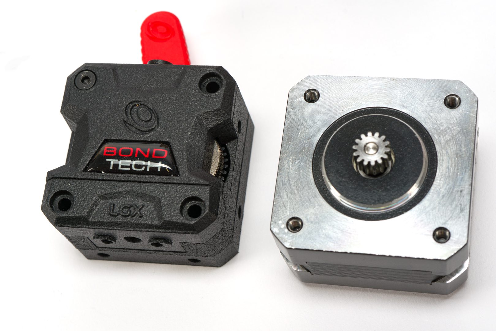
Separate the LGX extruder from the stepper motor
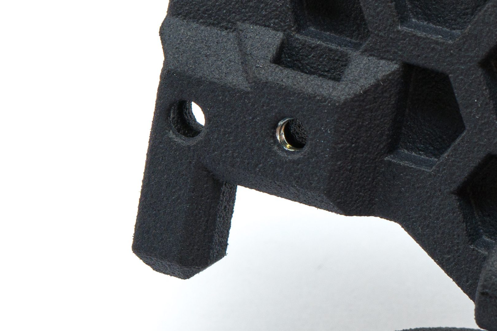
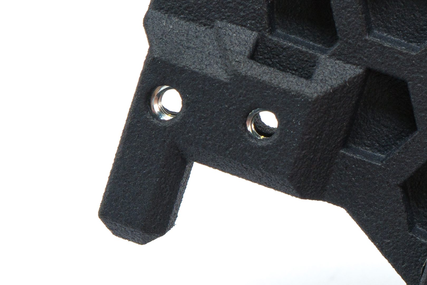
Step 2.3 Install Aluminum mount plate
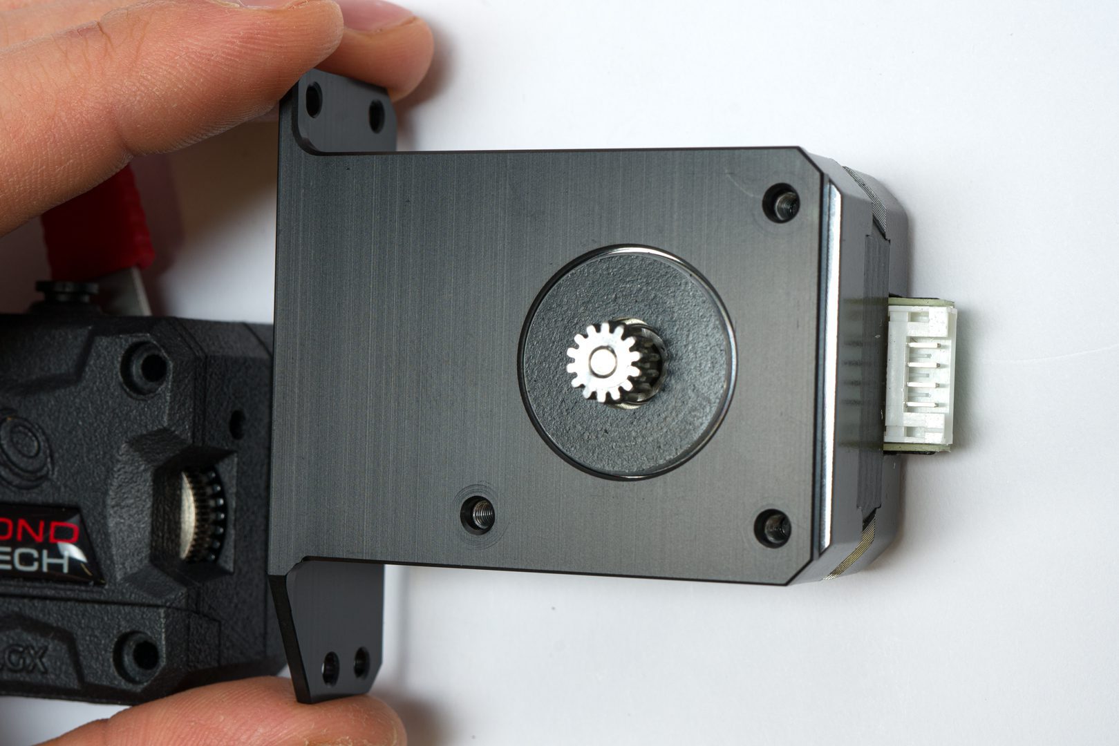
Place the mount plate on the stepper motor
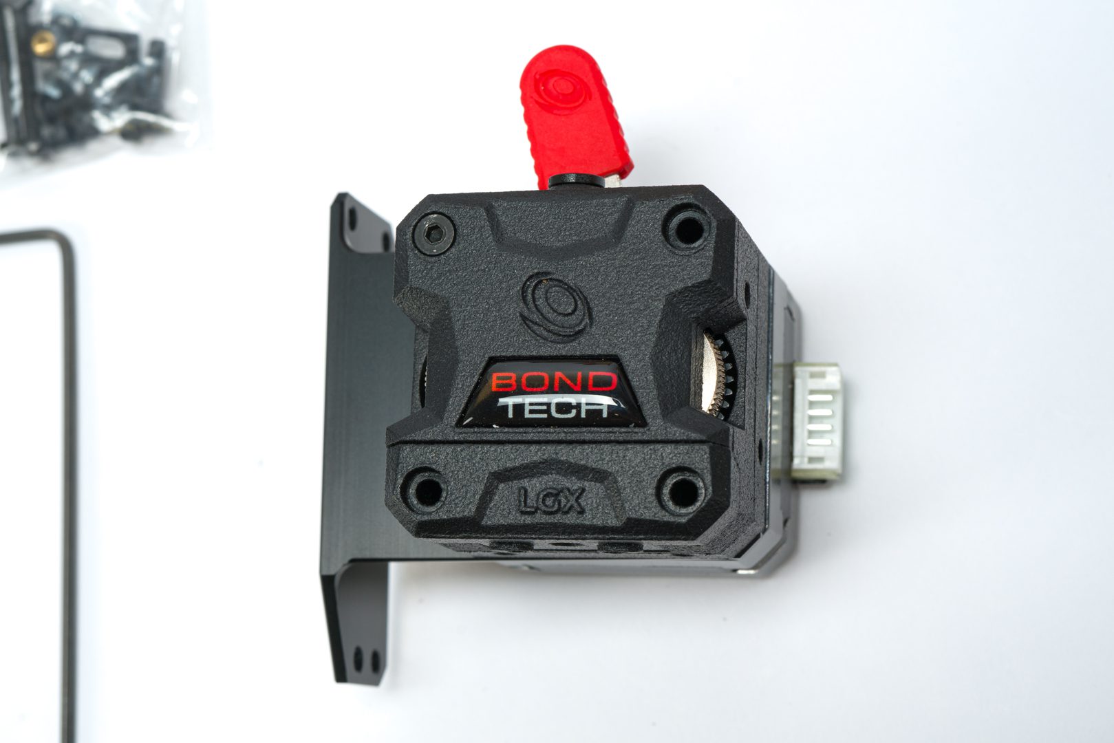
Align the holes of the LGX and mount
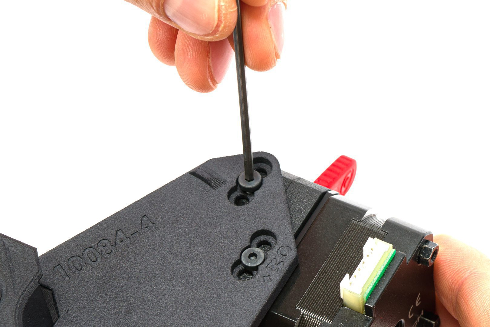
Use a longer M3x30 low head screw on the top right corner
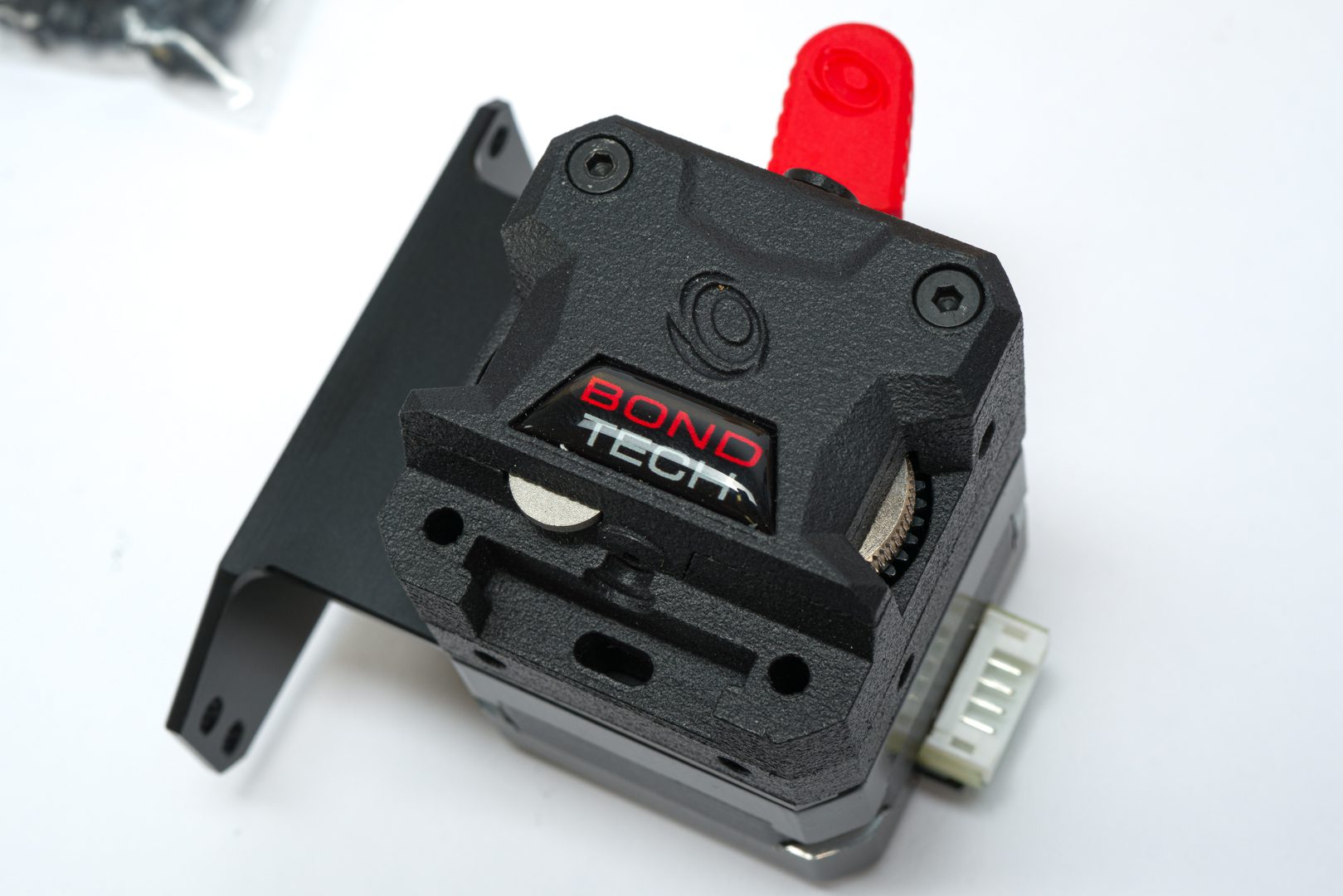
Remove the LGX interface plug and set it aside
Step 3.0 Be sure to have all the necessary tools and items
Tools you will need:
- Hobby knife;
- Torque Wrench to limit the tightening Torque to 1.5Nm;
- 2.5mm hex key.
Mosquito components you should have + nozzle:
- Mosquito hotend (with nozzle);
- 2x M2.5x6 screws (from Mosquito mounting hardware kit);
LGX components you should have:
- 2x M3x28 screws (from LGX);
Other components you should have:
- PTFE Tube
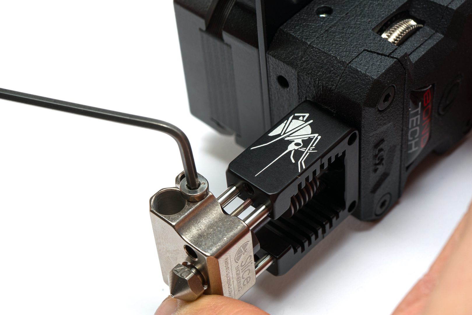
Step 3.1 Attach hotend to interface plug

Fit the top pf the Mosquito in the LGX interface plug mounting pattern
Attach them together using the 2 M2.5x6 screws
Tighten the screws to prevent any wiggling motion
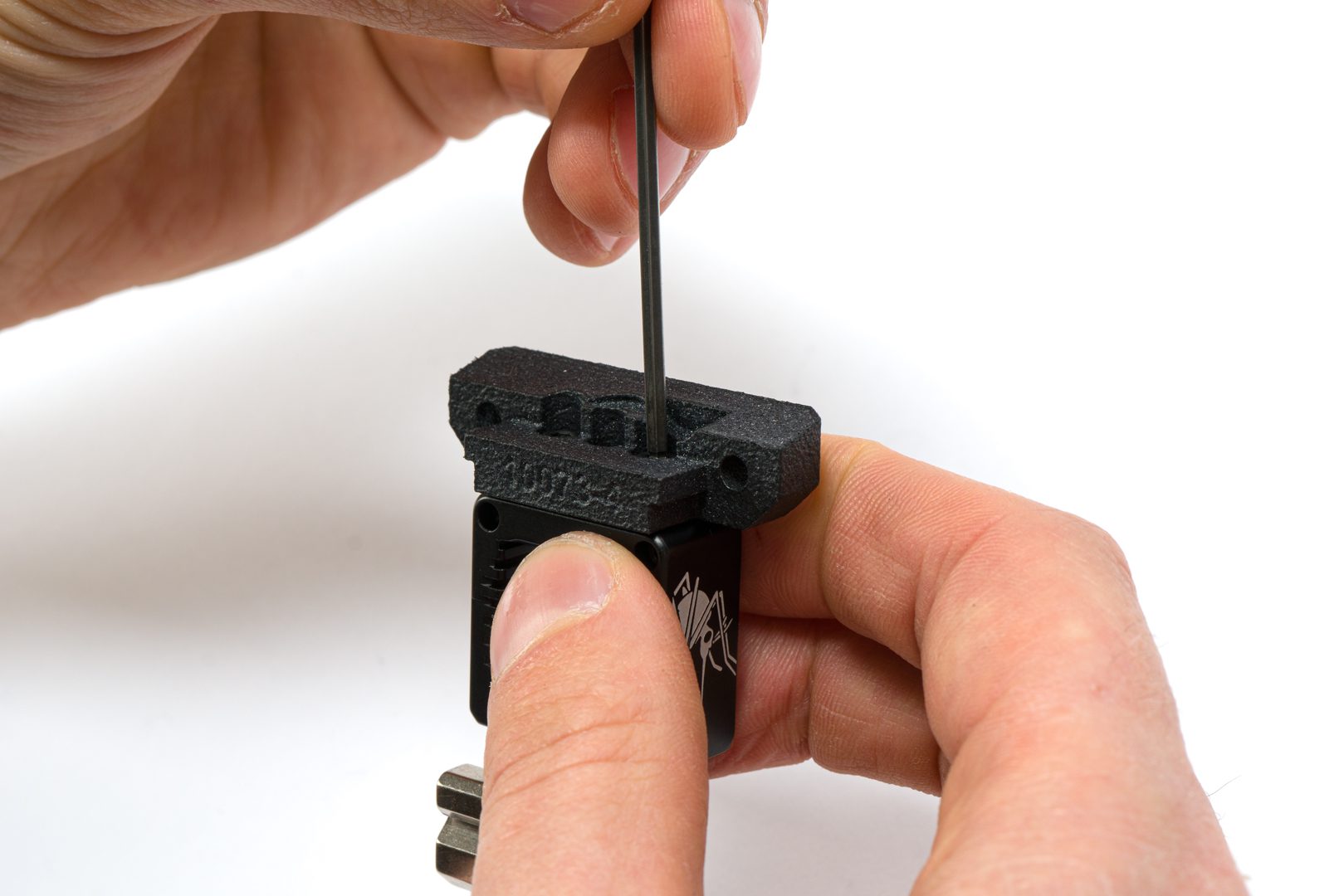
Step 3.2 Install the PTFE tube
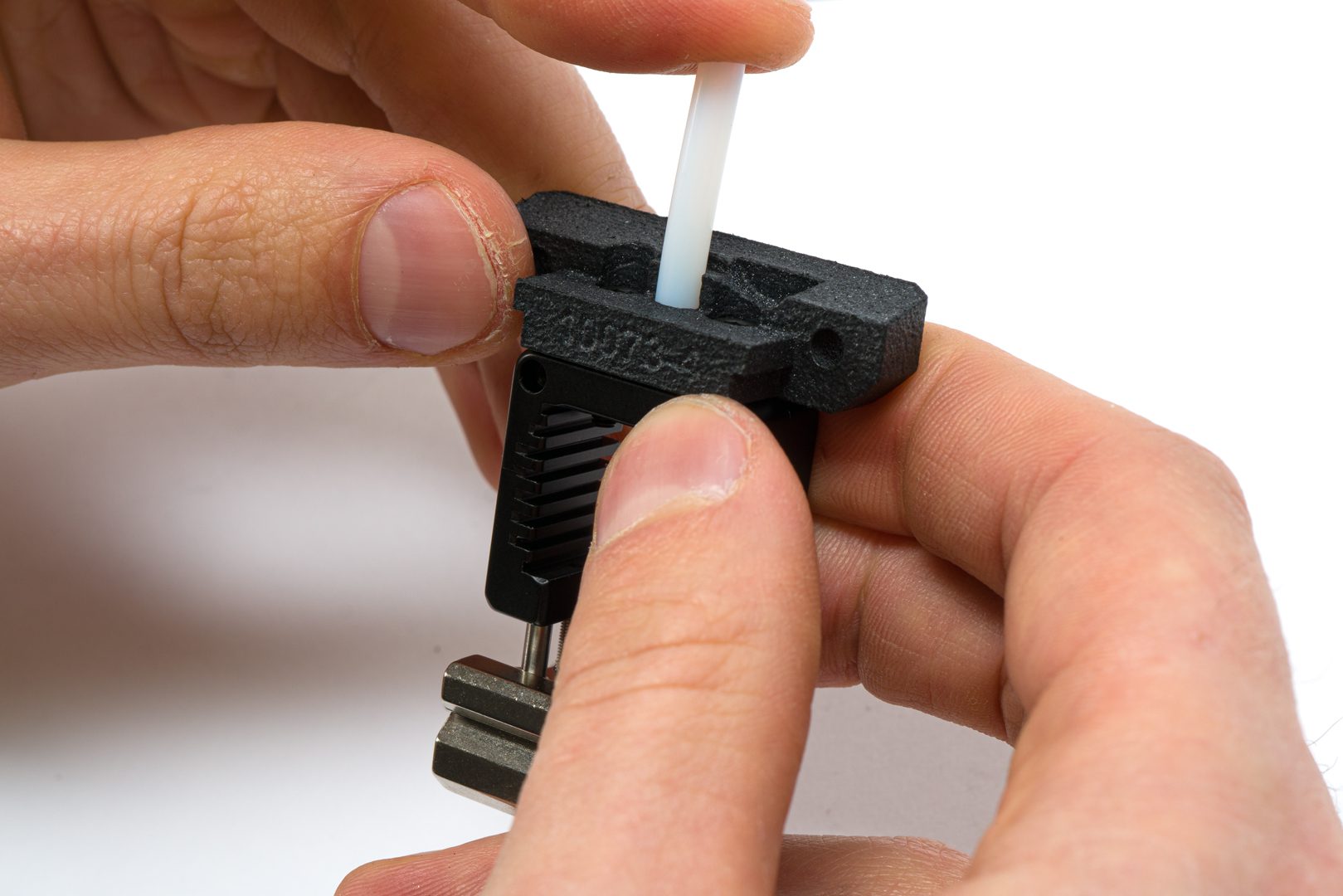
Insert the PTFE tube through the interface plug all the way down
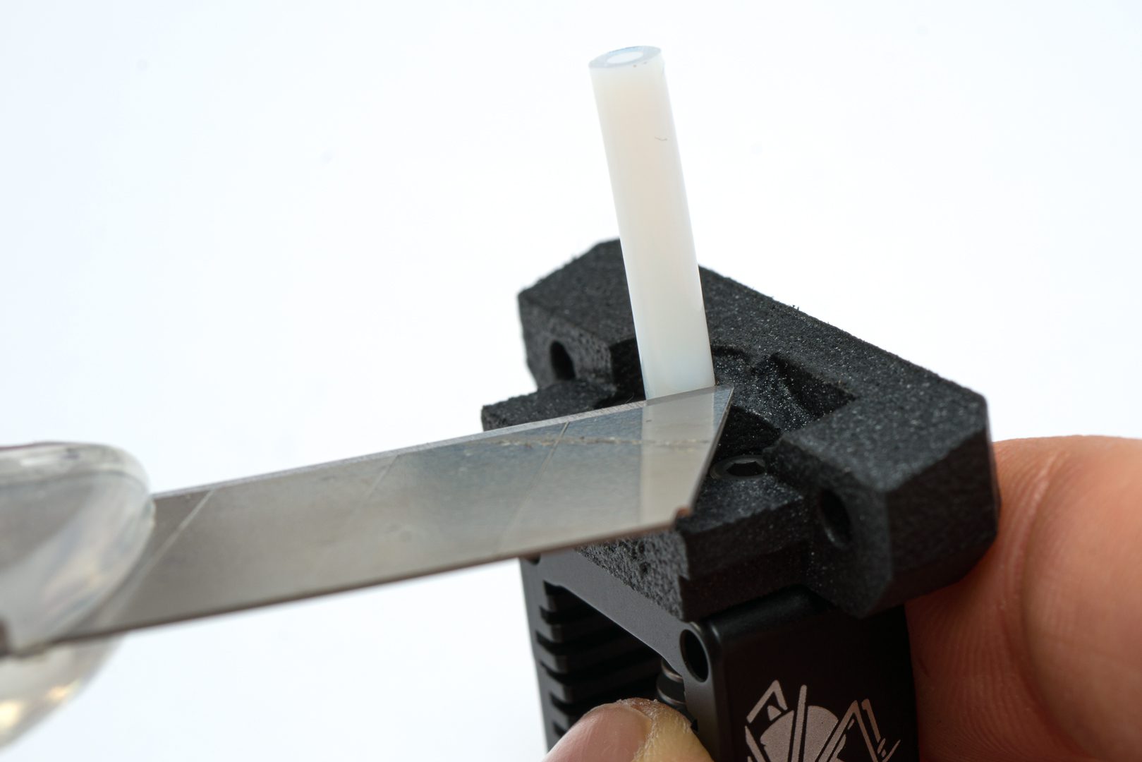
Use the hobby knife to cut the PTFE tube
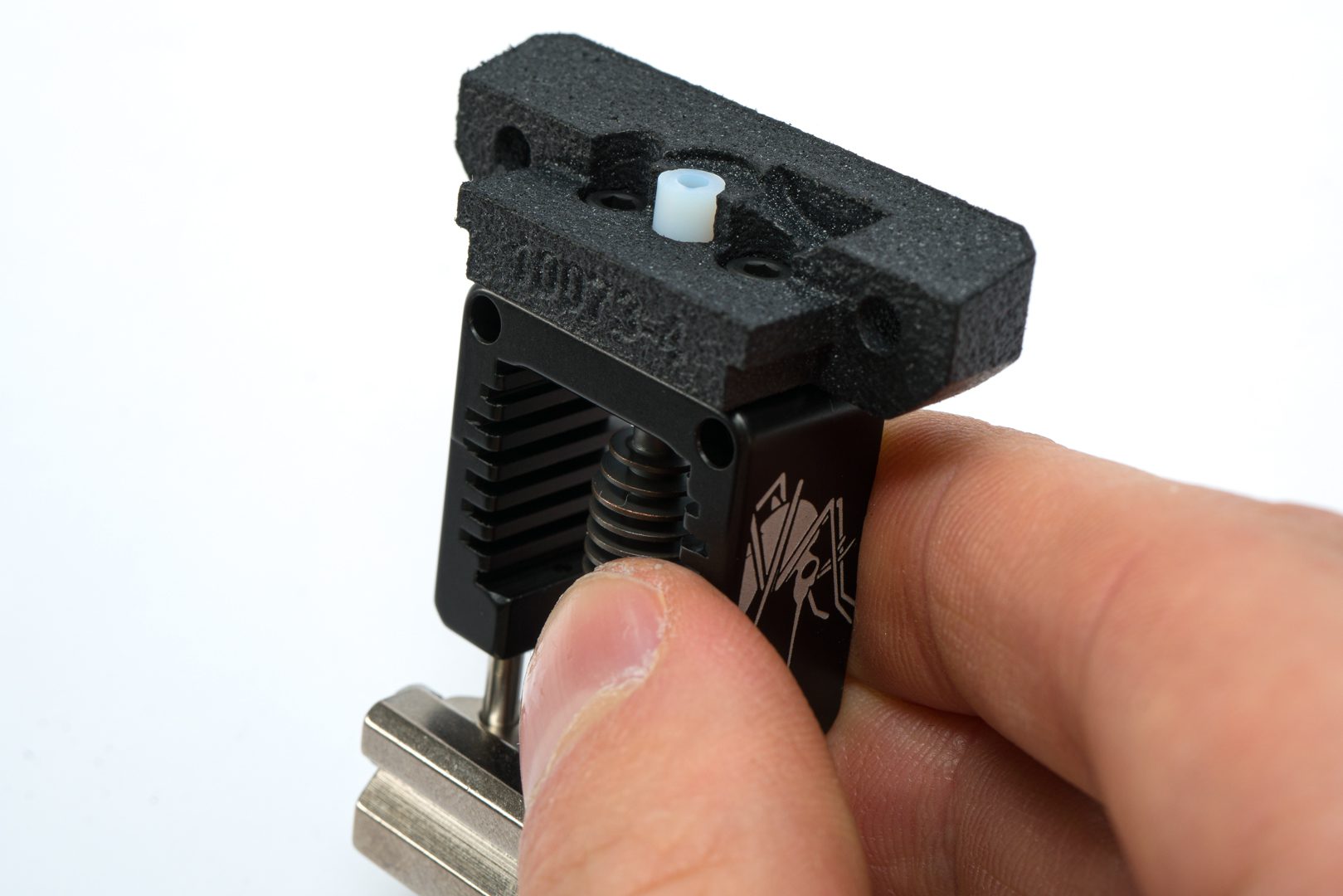
Cut it flush with the interface plug's top surface
Step 3.3 Install hotend on LGX
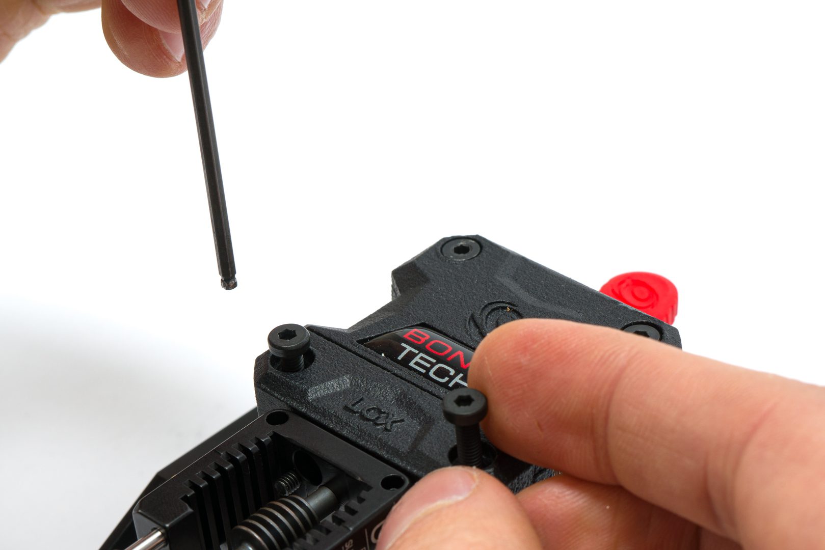
Fit the interface plug into the LGX and place the M3x28 screws
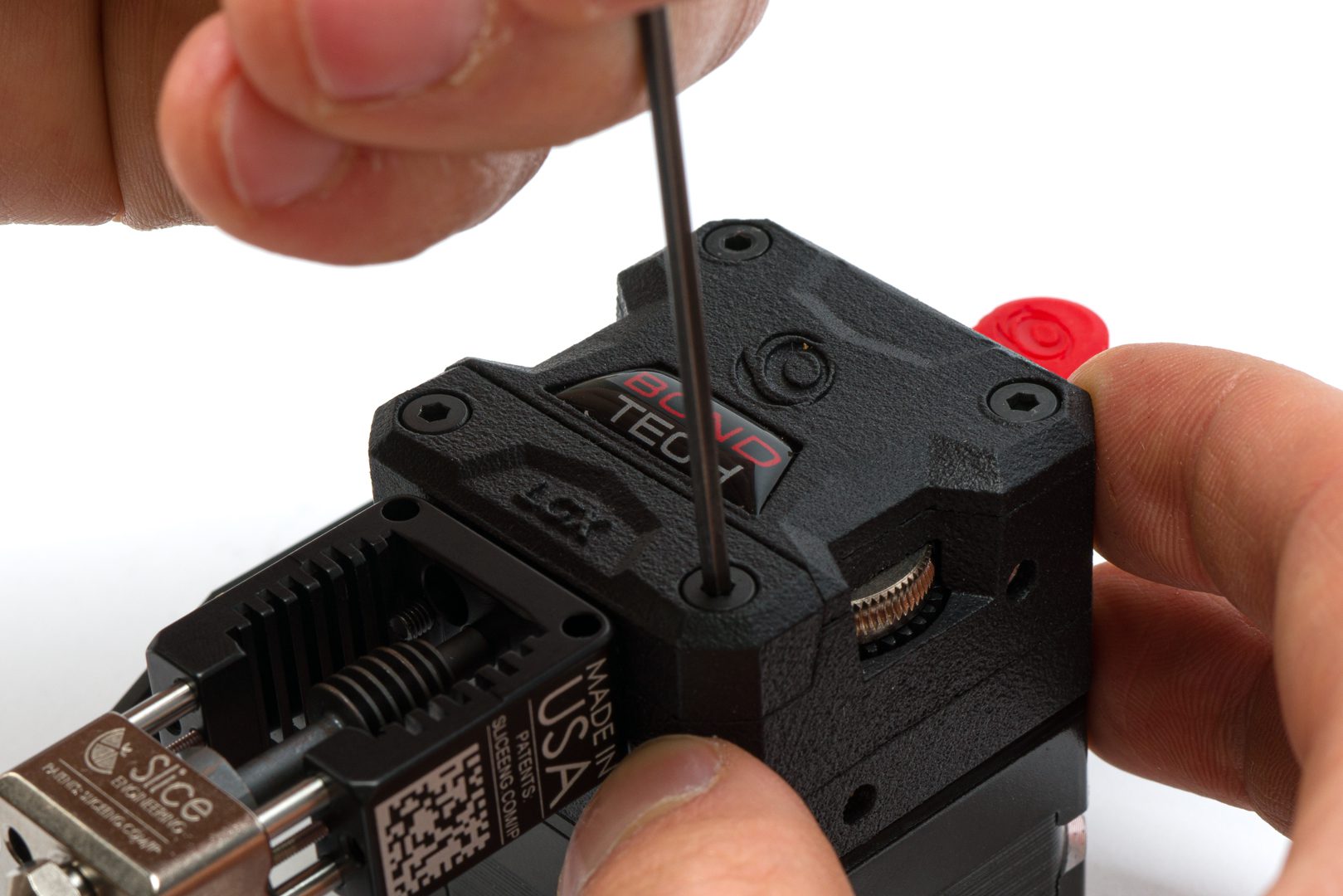
Tighten the screws using the 2.5mm hex key
Step 3.4 Install Heater and Thermistor
Install the Bondtech heater and stock thermistor
Remove the cartridge retention screw
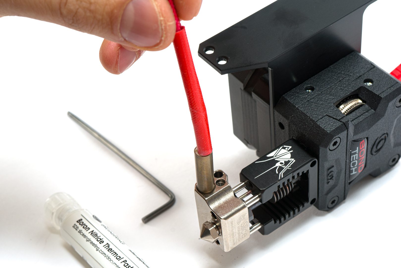
Coat the heater cartridge with Boron Nitride Paste and insert it in the heater hole
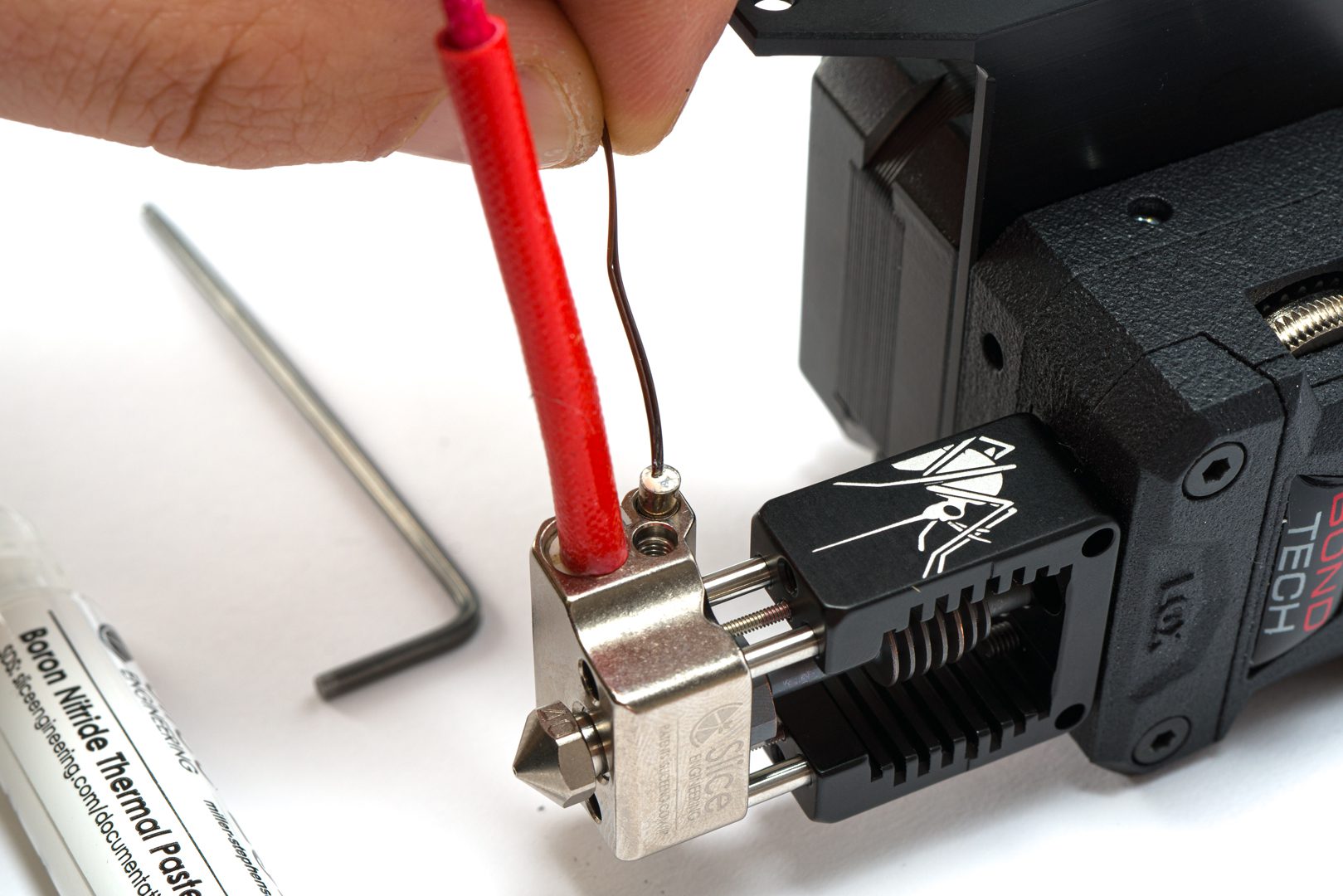
Coat the thermistor cartridge with Boron Nitride Paste and insert it in the thermistor hole
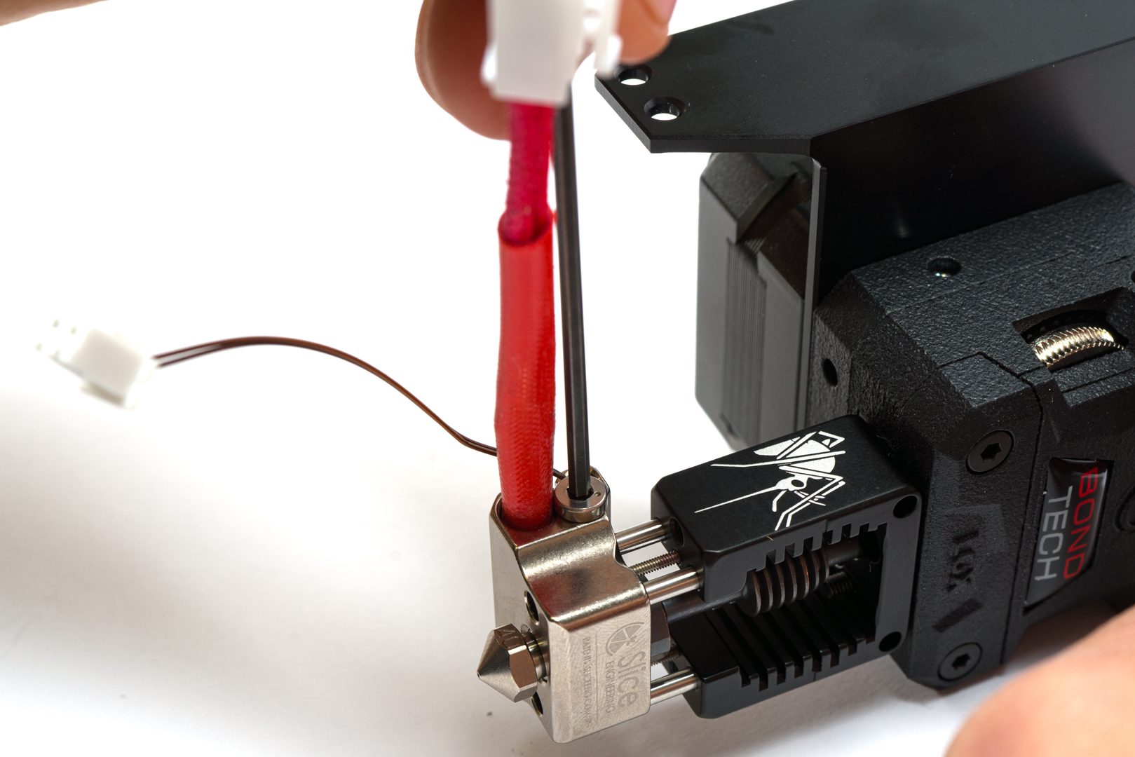
Tighten the retention screw
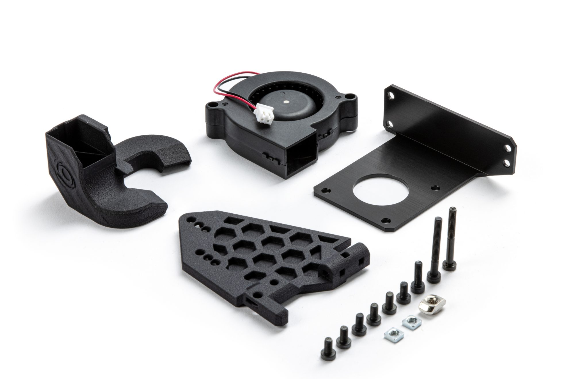
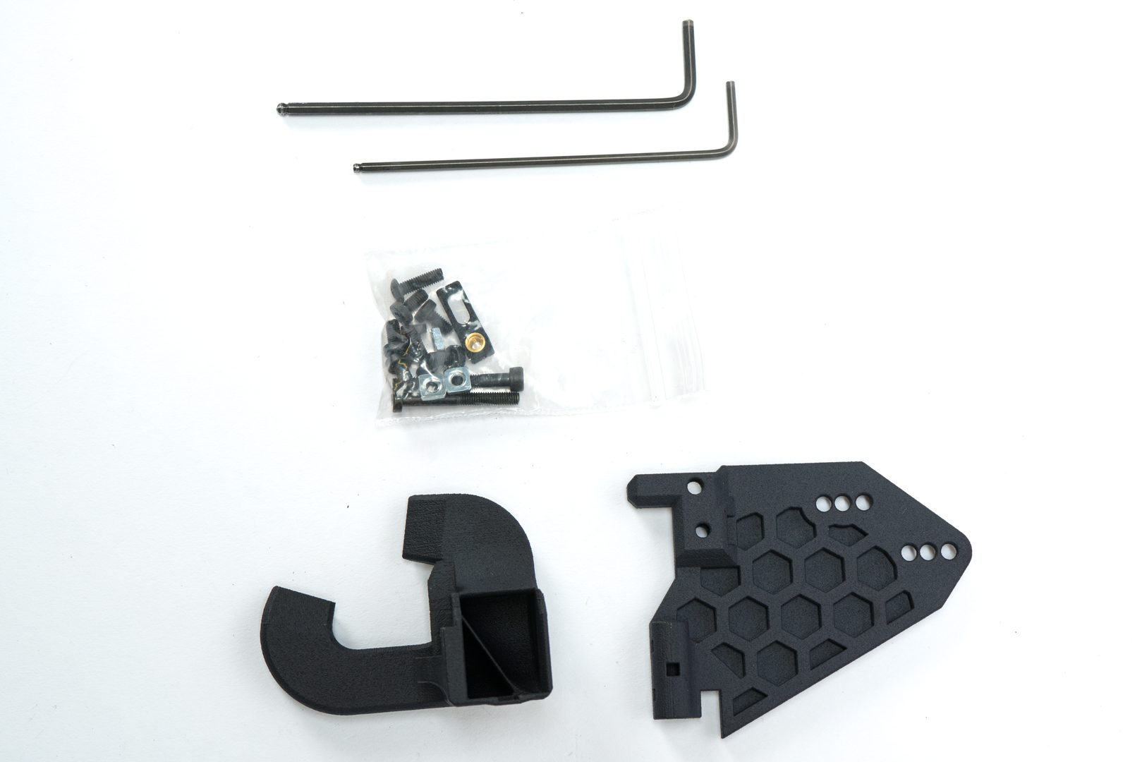
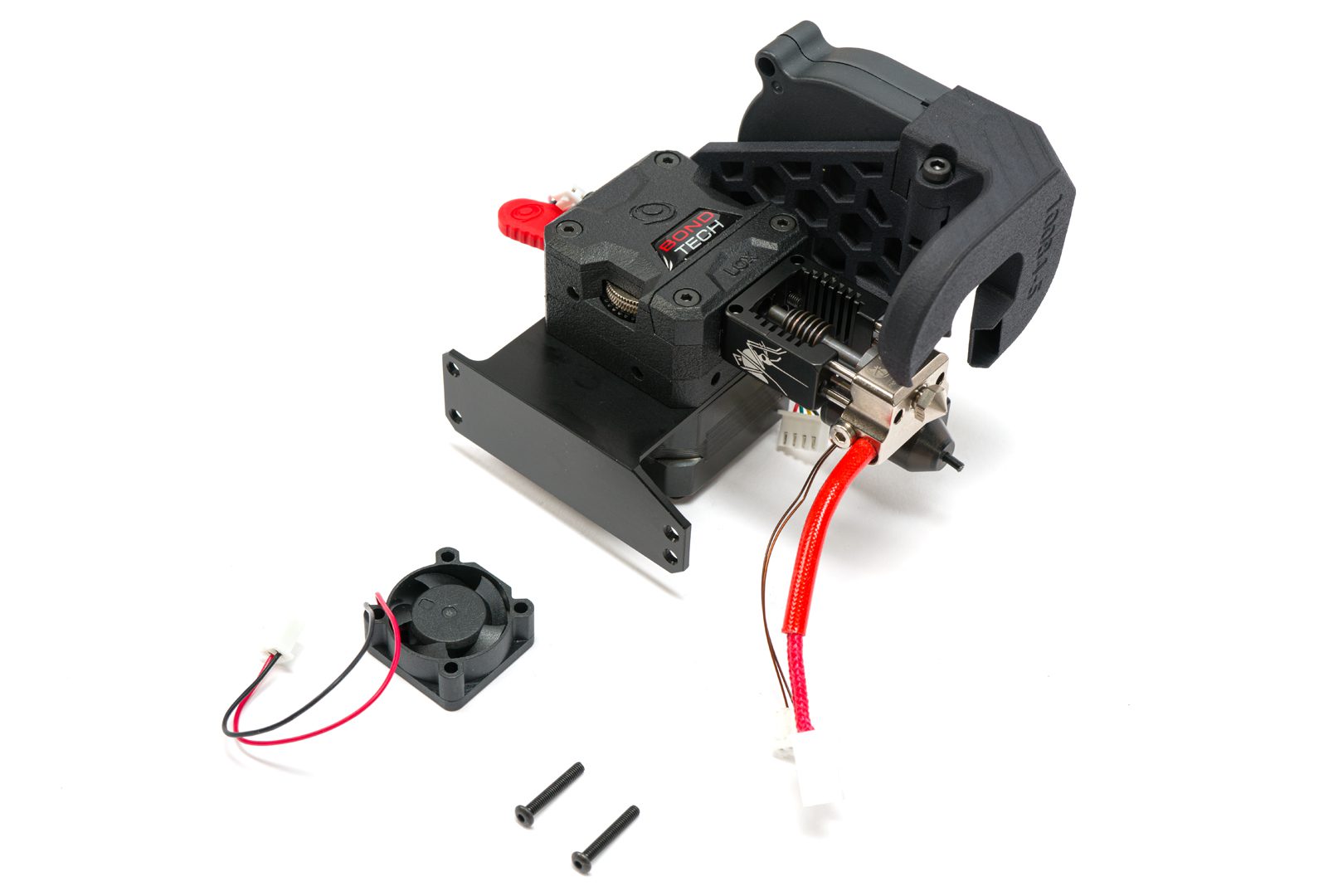
Step 4.0 Verify You have these items
To move forward verify you have the following
tools :
- 2.0 hex key;
- 2.5 Hex Key.
Accessories :
- Mounting hardware;
- Fan mount;
- Fan Shroud;
- 5015 fan.
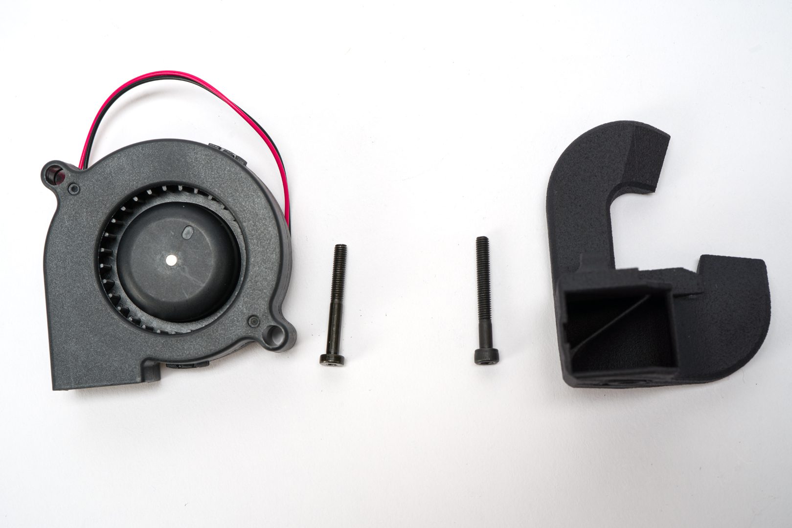
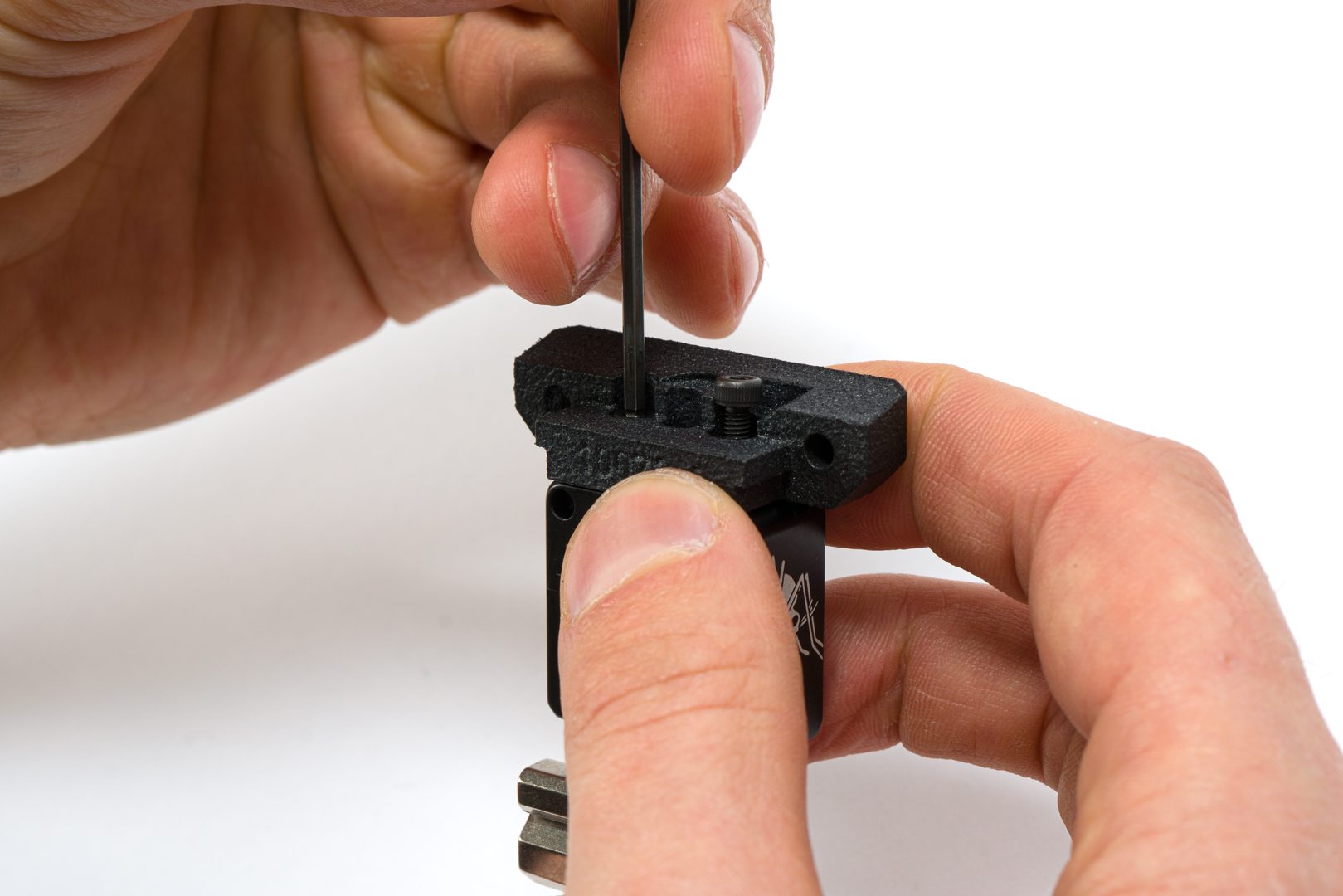
Step 4.2 Assembling the fan mount on the fan shroud
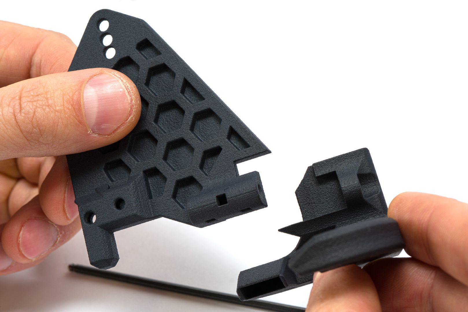
Take the fan mount and fan shroud
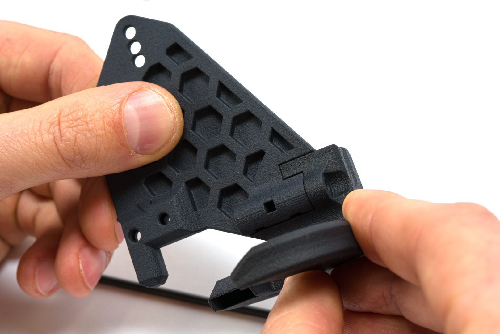
Fit the fan mount in the fan shroud
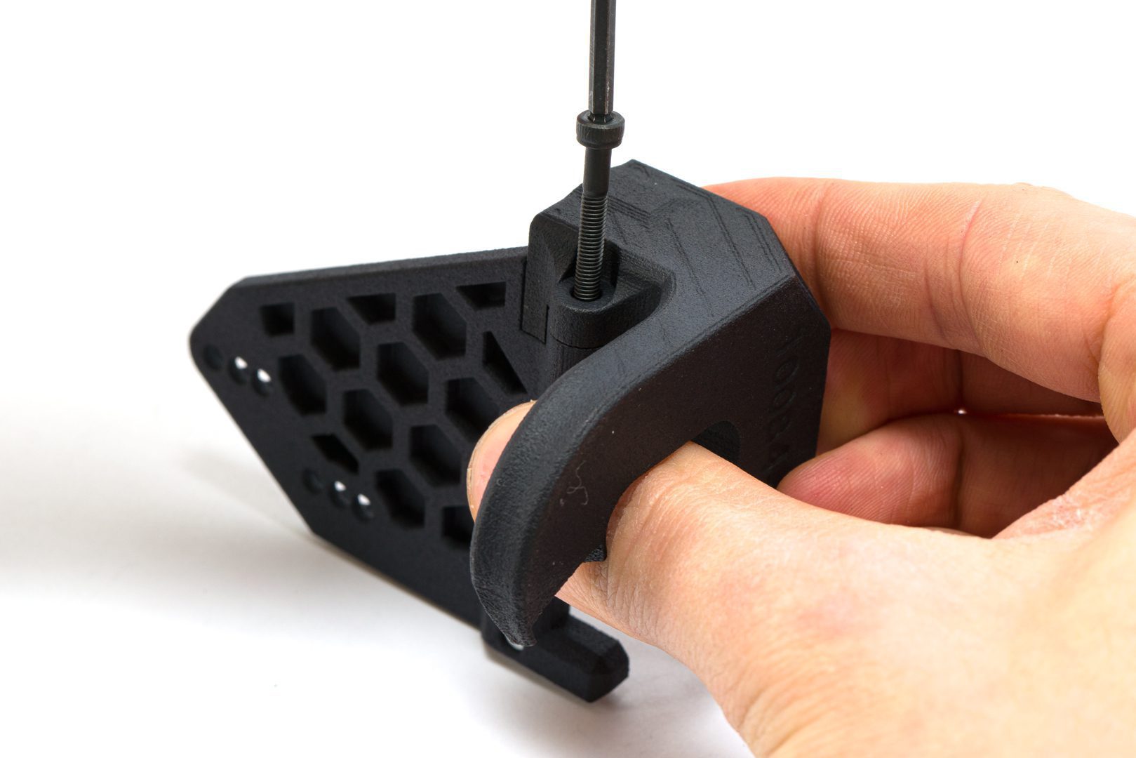
Use the M3x25 screw to attach them together
Use the 2.5 the key to tighten the screw
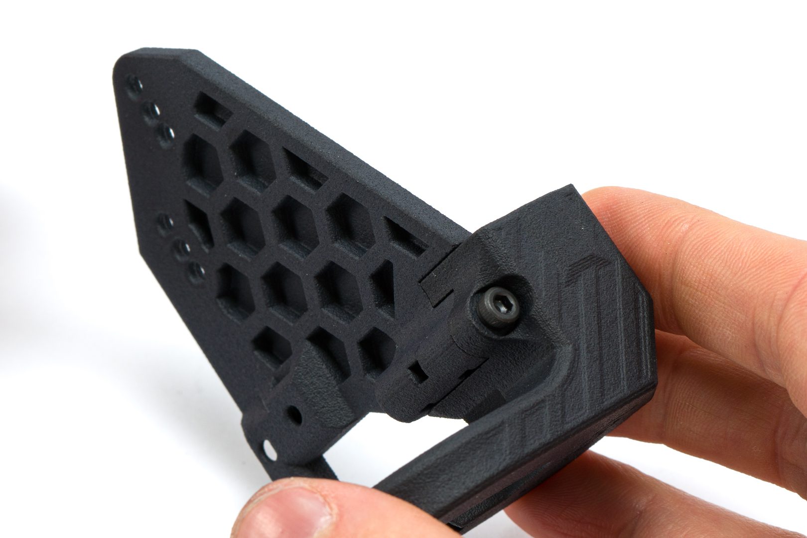
Assembly stays like this
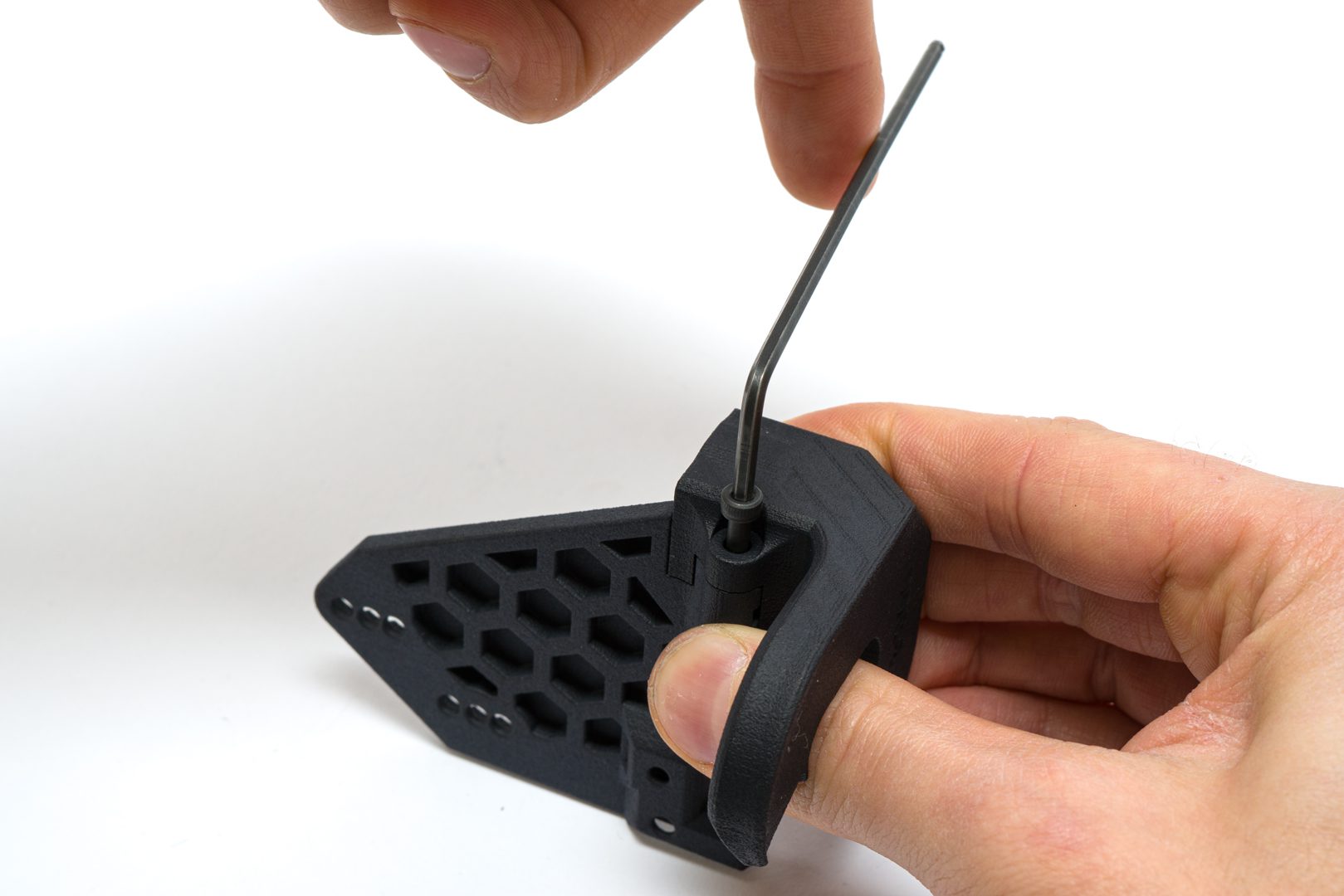
Step 4.3 Installing the square nuts
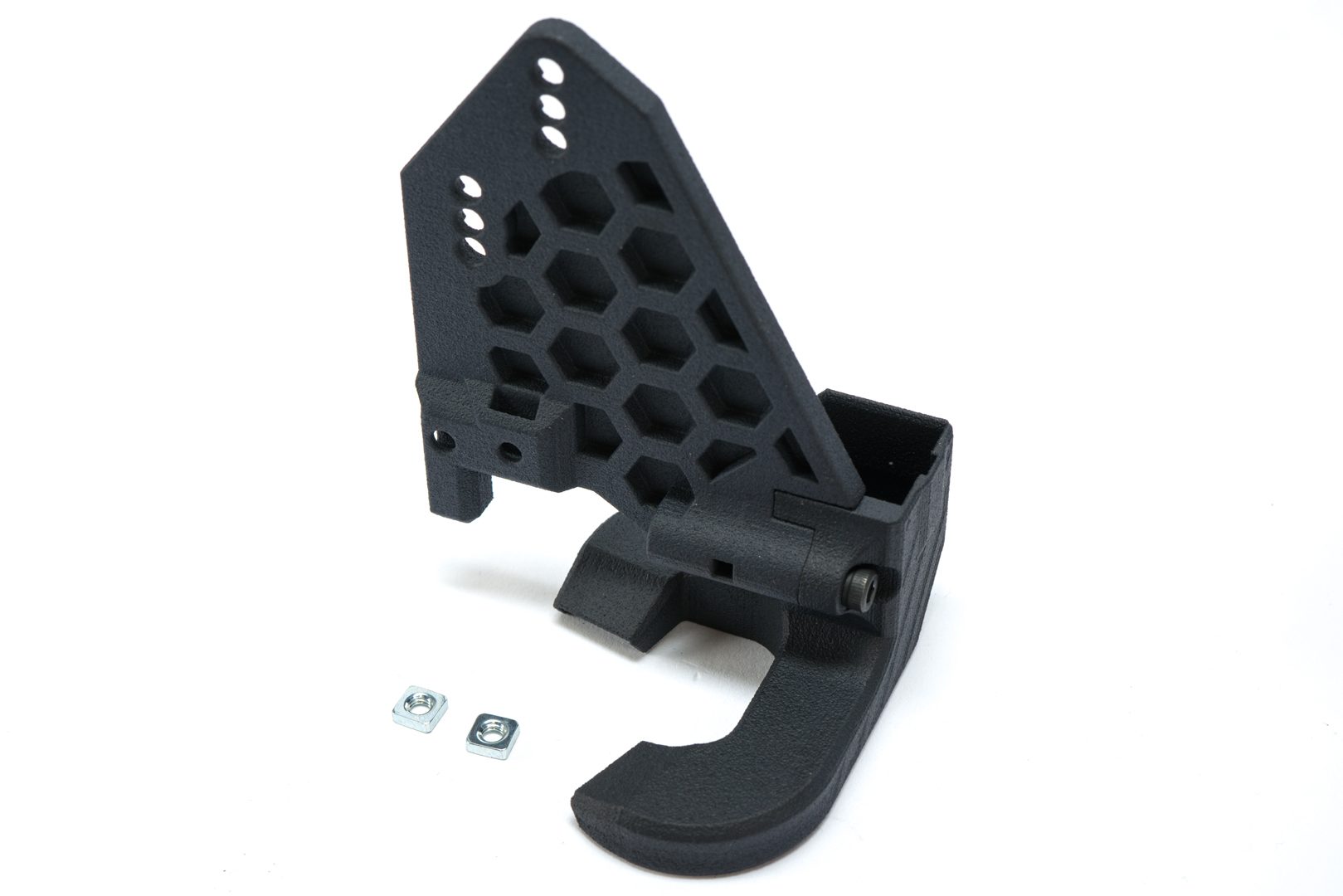
Use 2 square nuts
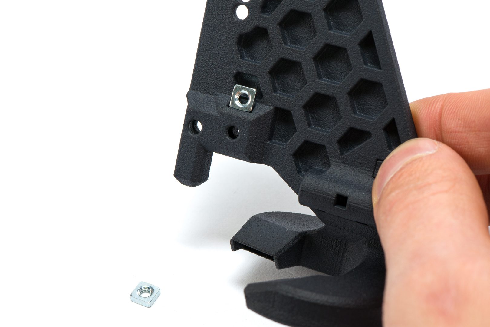
Insert one in the anterior top pocket
Insert another in the anterior side pocket
Square nuts stay like this
Step 4.4 Mounting the LGX
Mind the markings near the fan mount holes:
- C for Copperhead;
- M for Mosquito;
- + for Magnum+
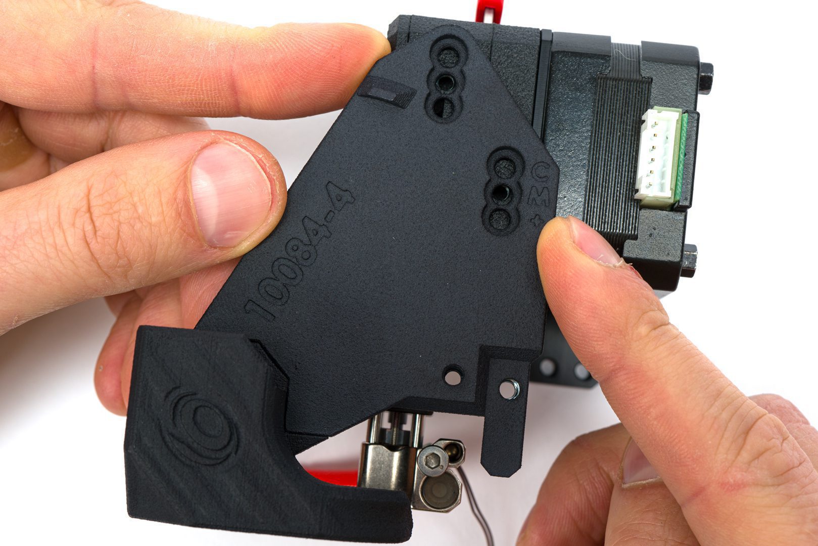
Depending on your hotend, align its mounting holes with the LGX mounting pattern
Tighten the fan mount to the LGX using 2 M3x6 screws
4.5 installing the bed levelling sensor
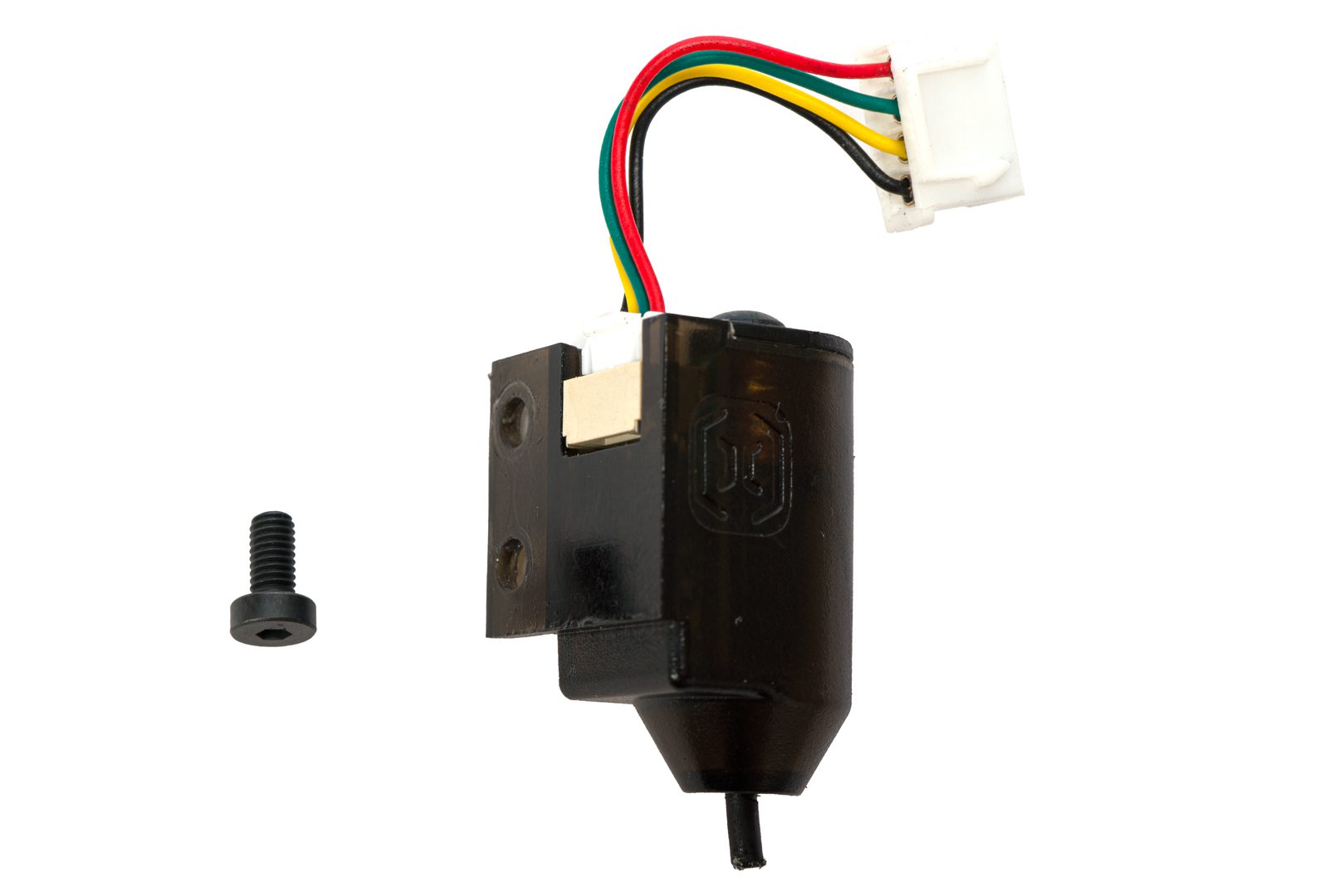
Take the Artillery levelling sensor and one M3x6 screw
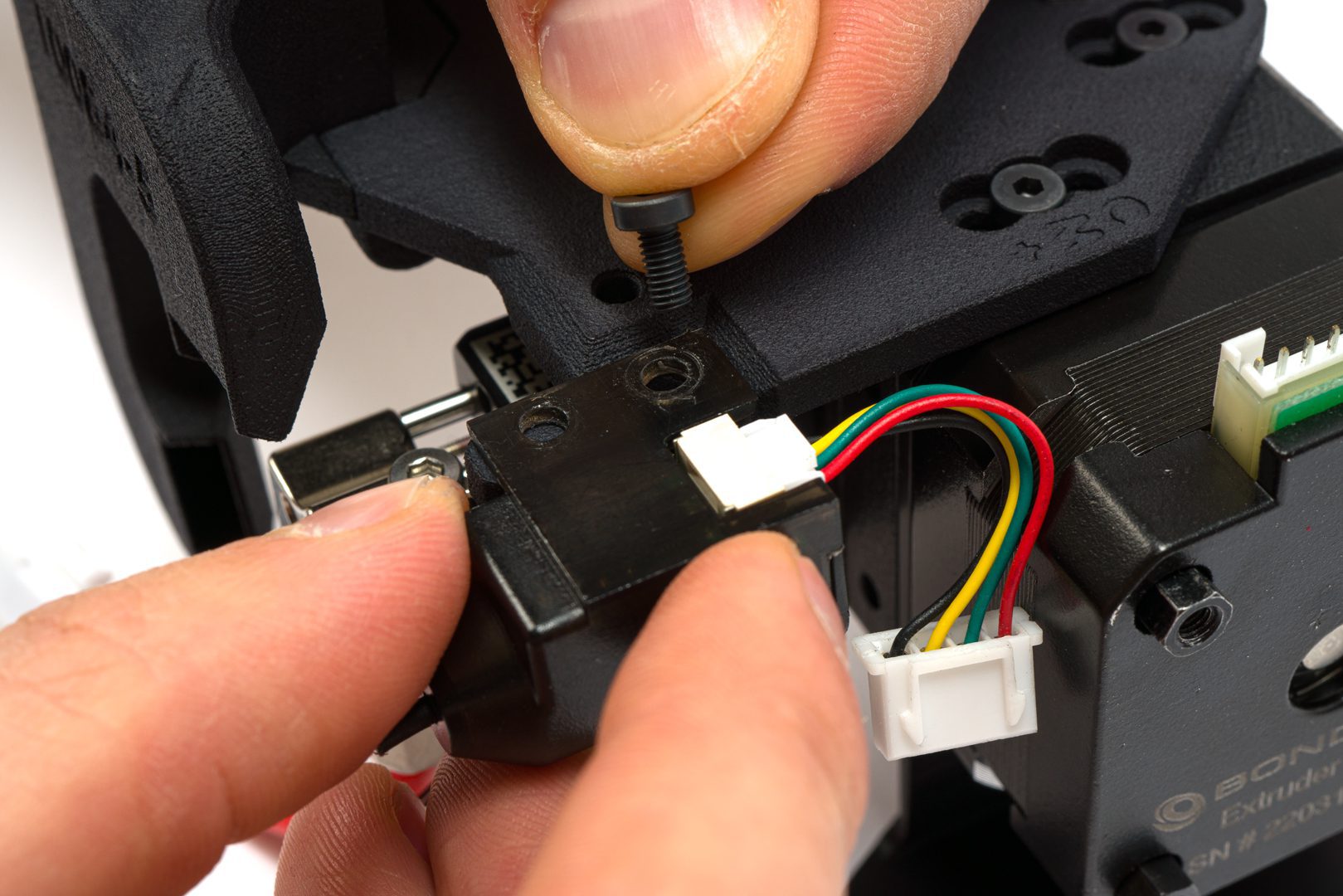
Align the mounting holes with the Artillery logo facing away from the fan mount
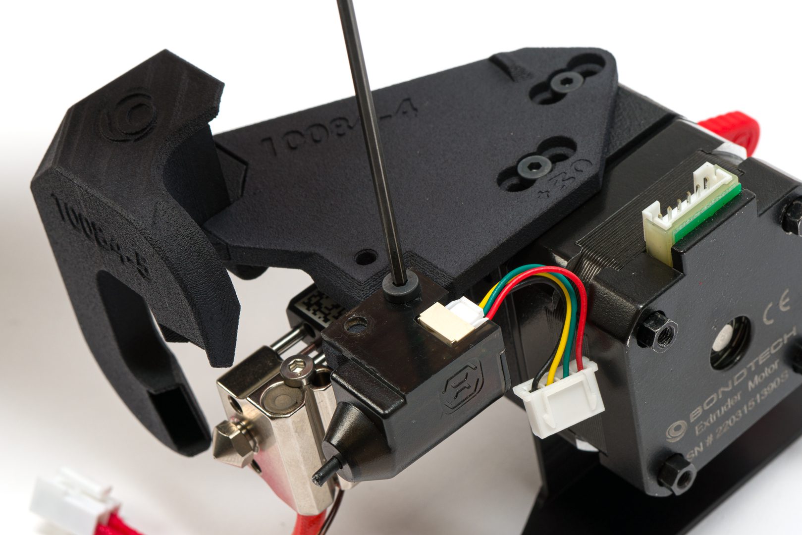
Tighten the screw using the 2.5mm hex key and this orientation
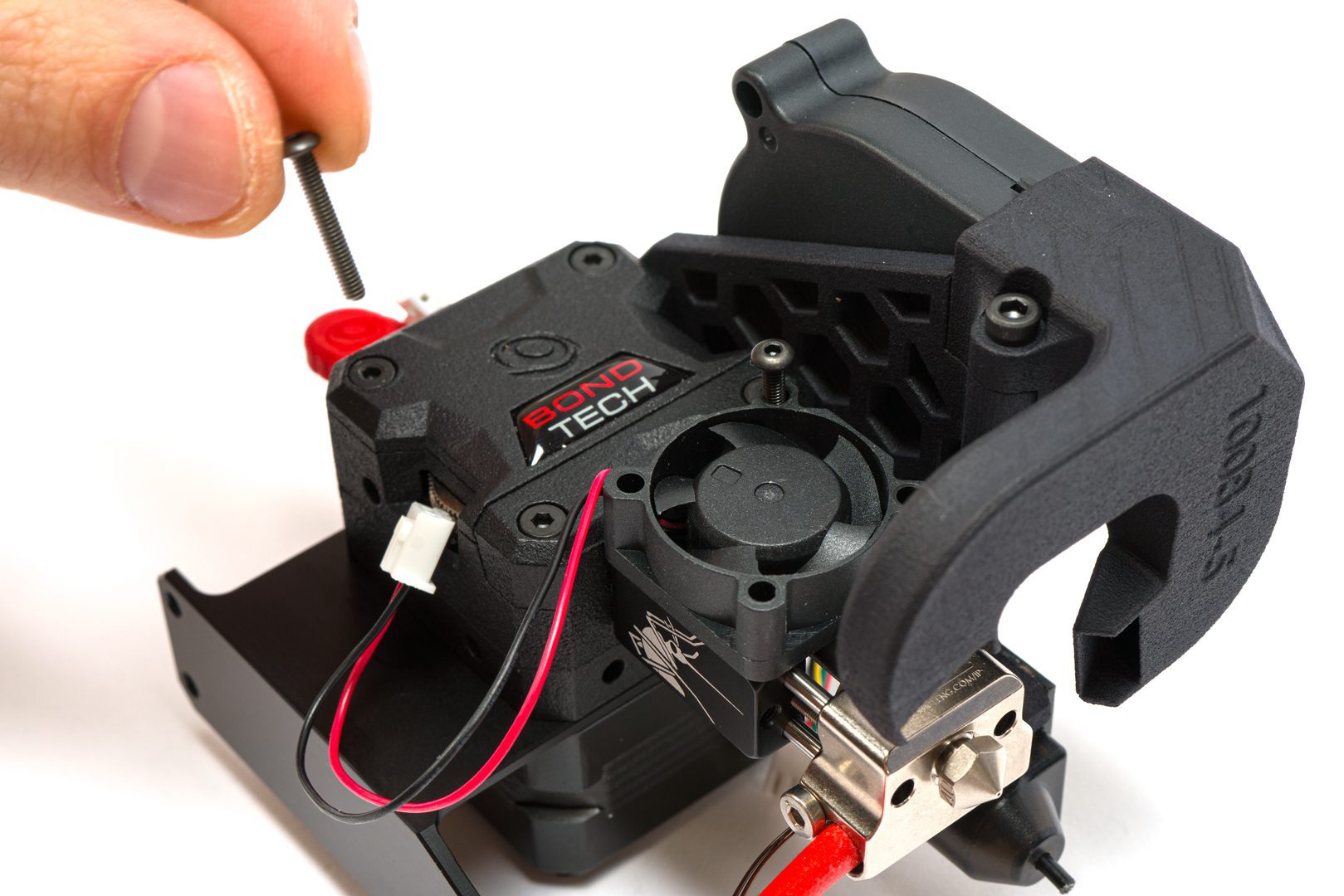
Step 4.6 Installing the 5015 radial fan
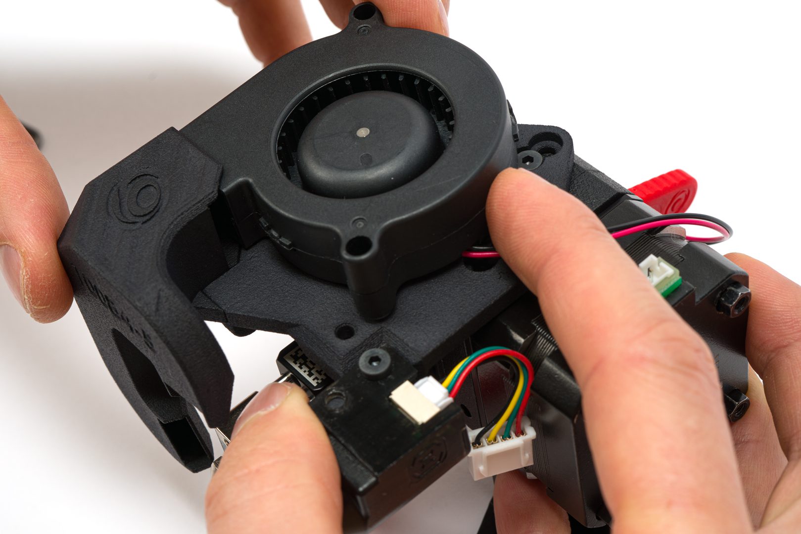
Aling the 5015 fan with the fan shroud and press it in
Rotate the fan to align it with the fan mount hole
Insert the M3x25 Low Head socket screw
Use the 2.5mm hex key to tighten the screw
Radial fan installed.
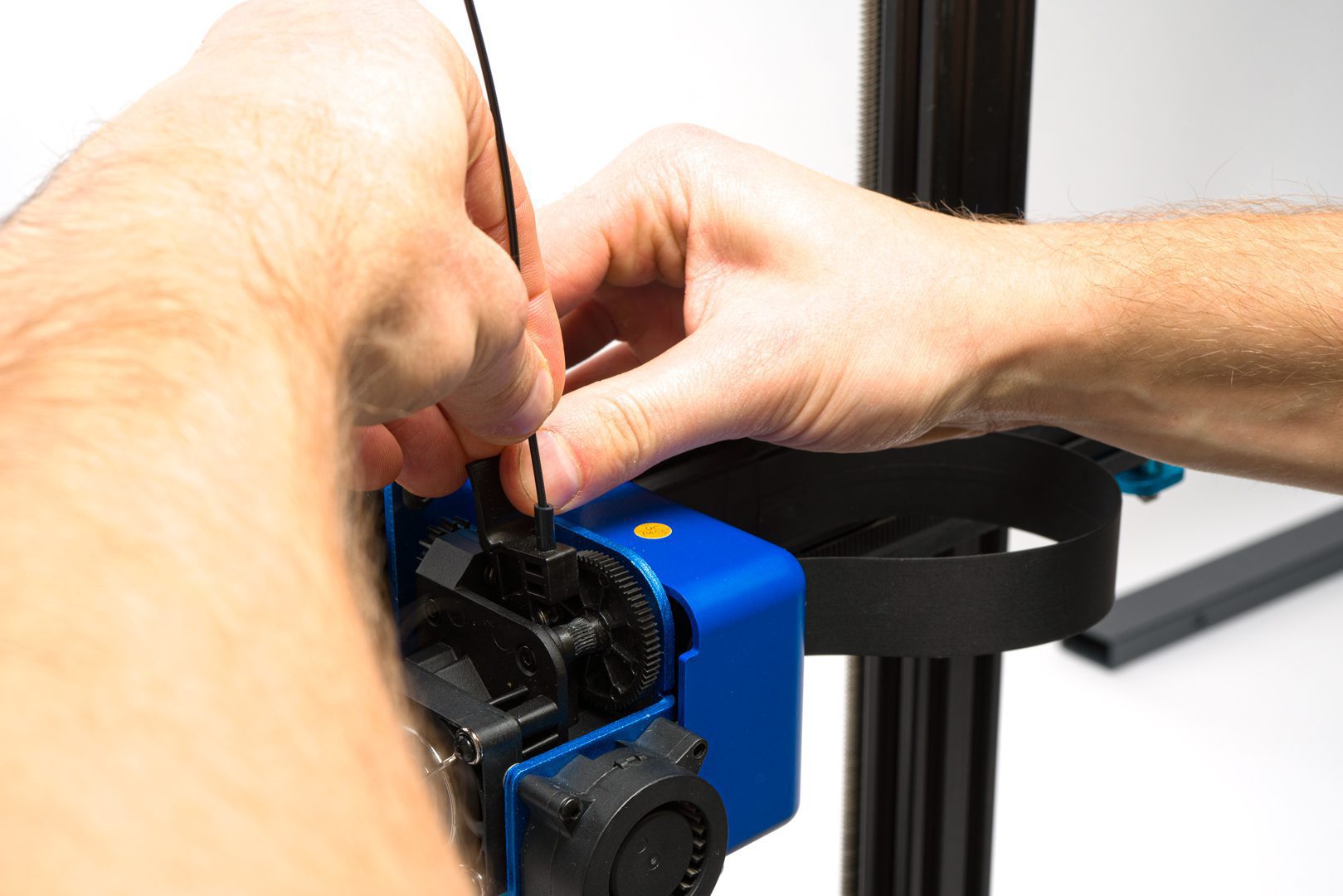
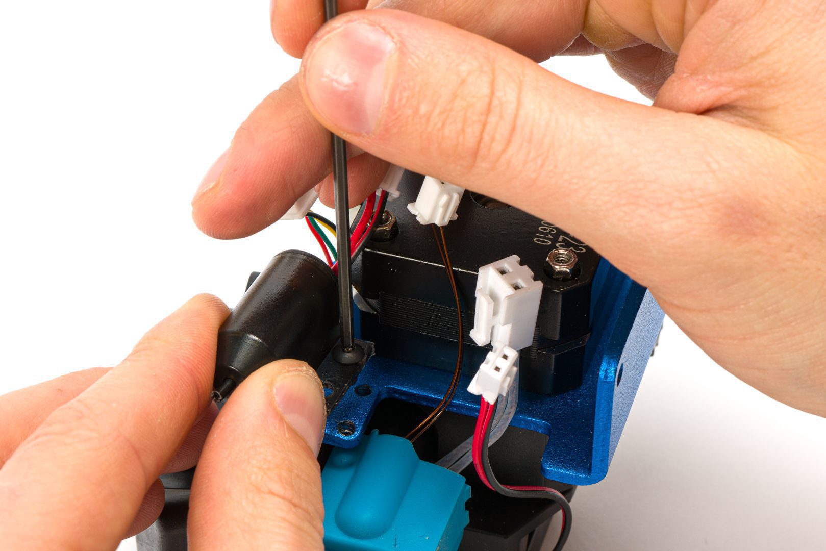
Step 4.7 Modifying the stepper motor cable
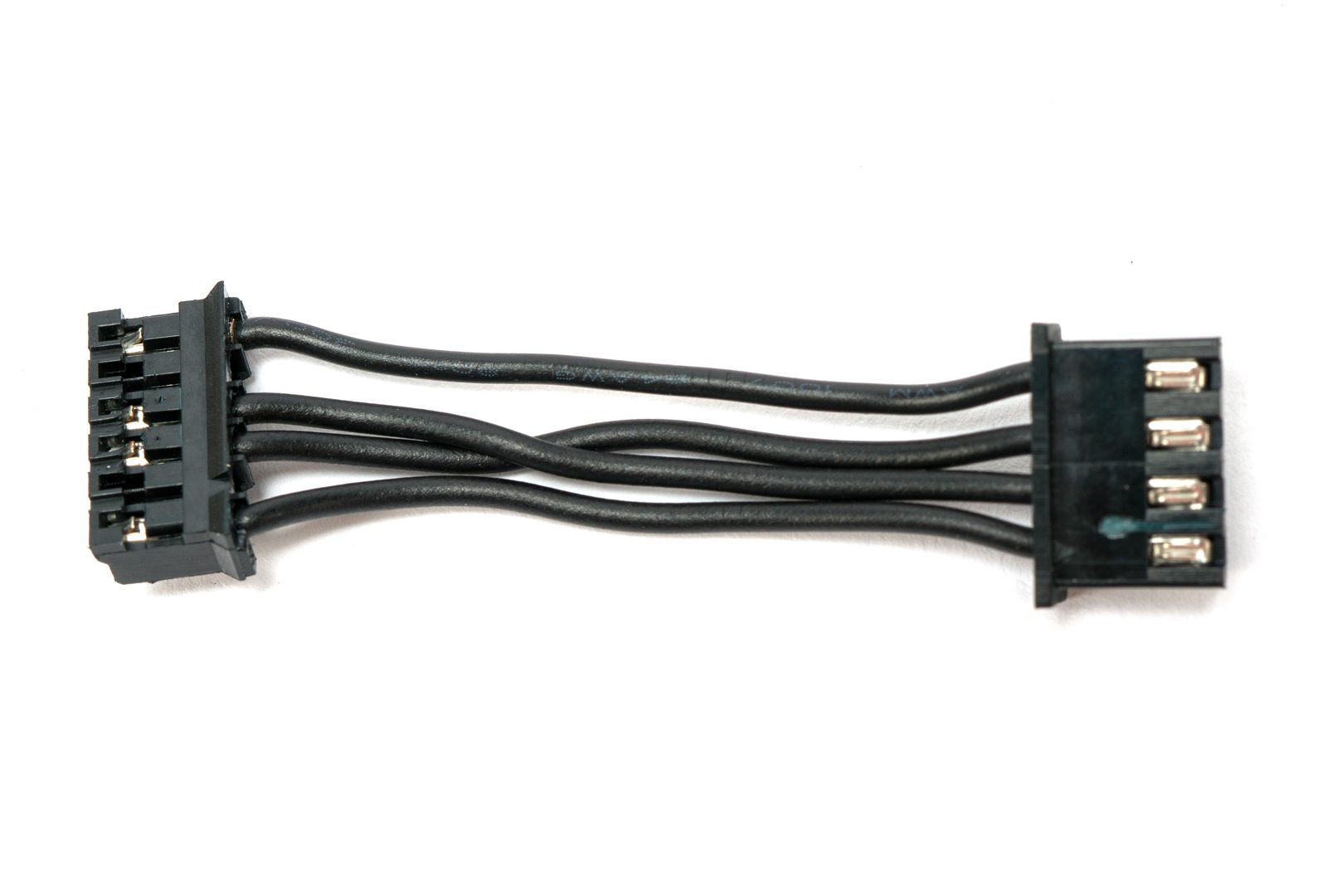
Take the stock stepper motor cable. Mind the middle wires twisted.
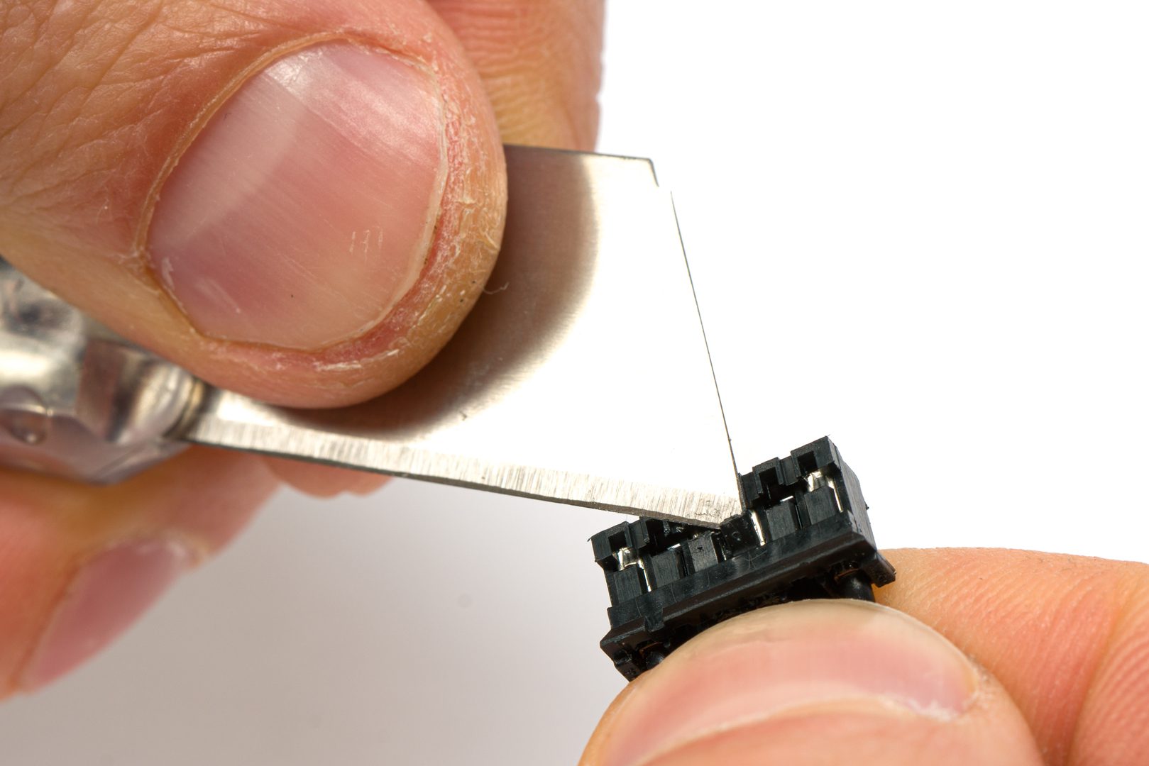
Use a sharp tip to lift the connector gripping teeth
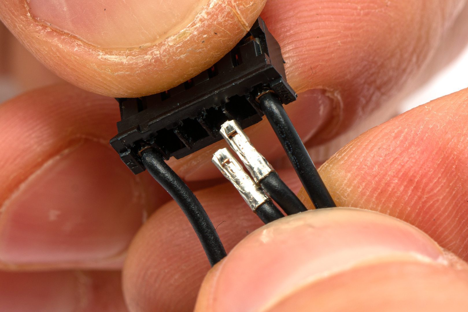
Remove the 2 middle wires
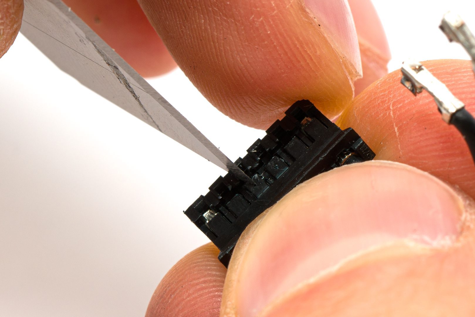
Untwiste them, but them back in and press the gripping teeth back down
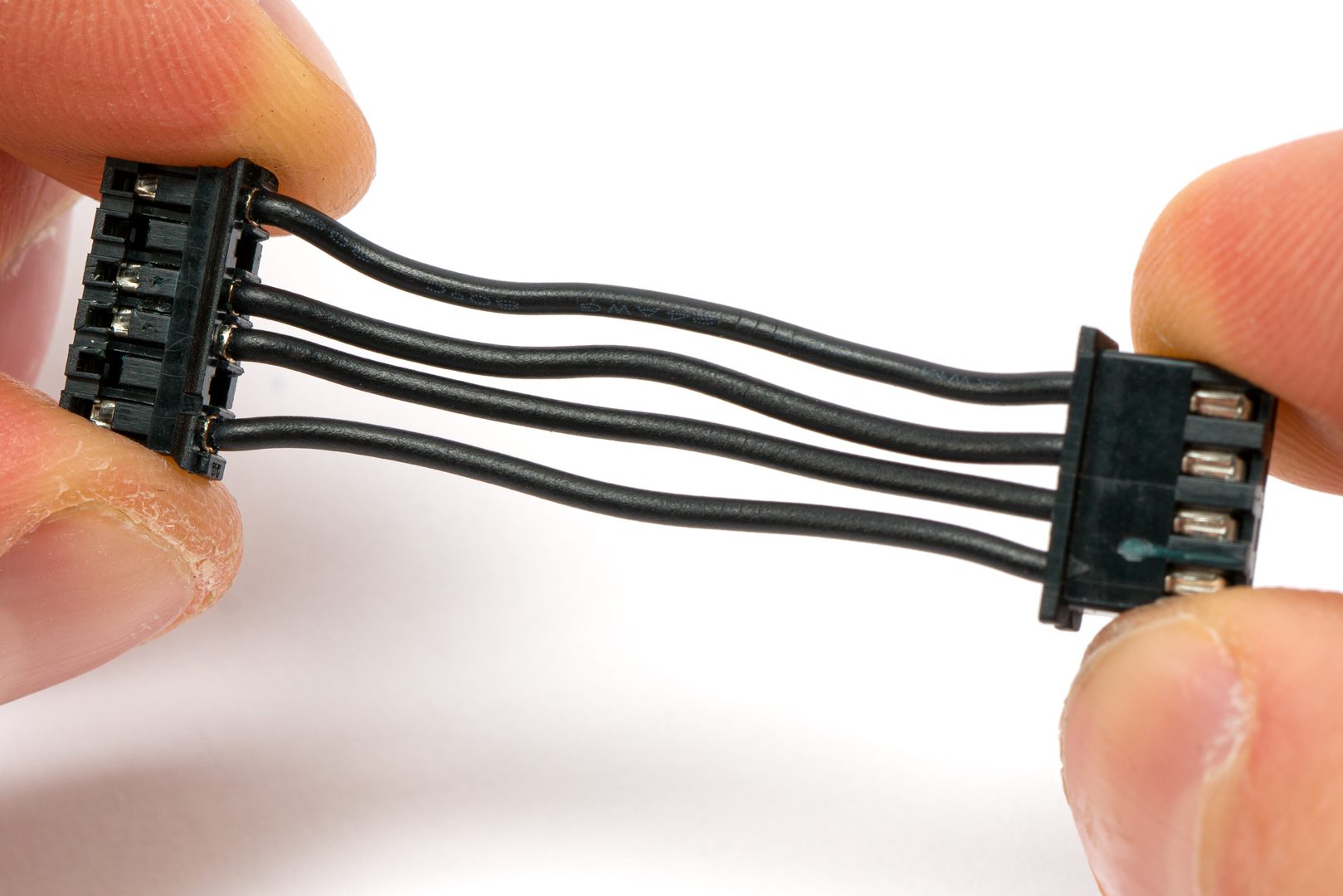
Cable should look like this after the modification
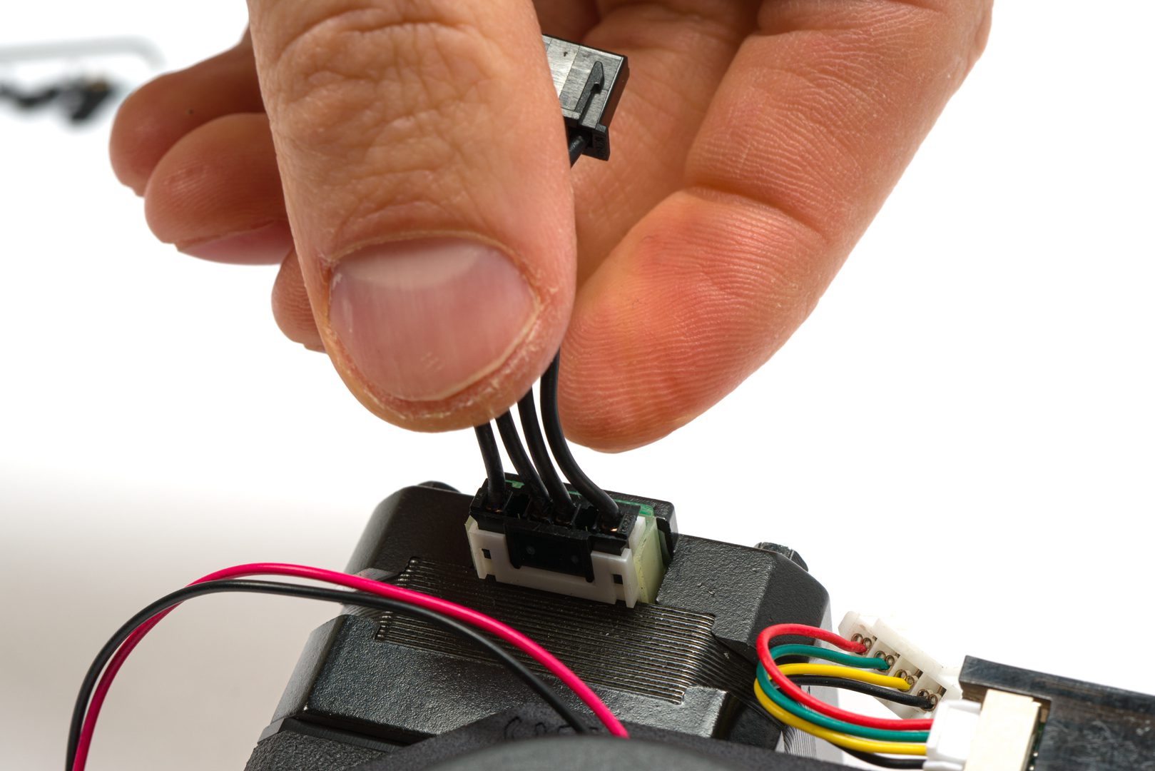
Plug the cable on to the LGX stepper motor
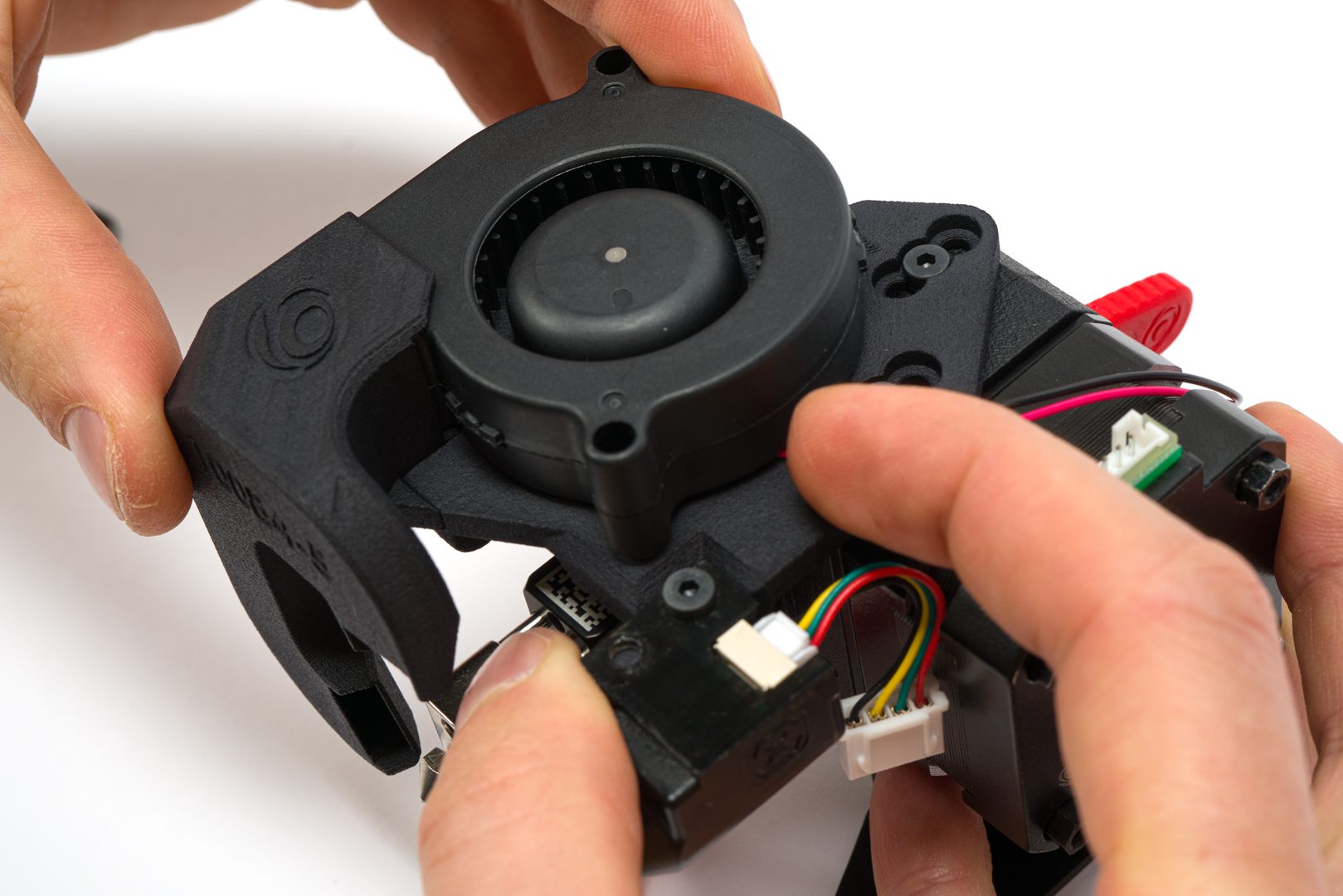
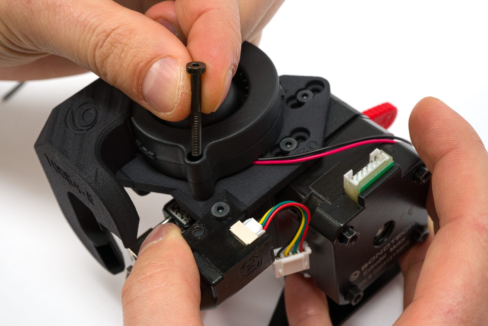
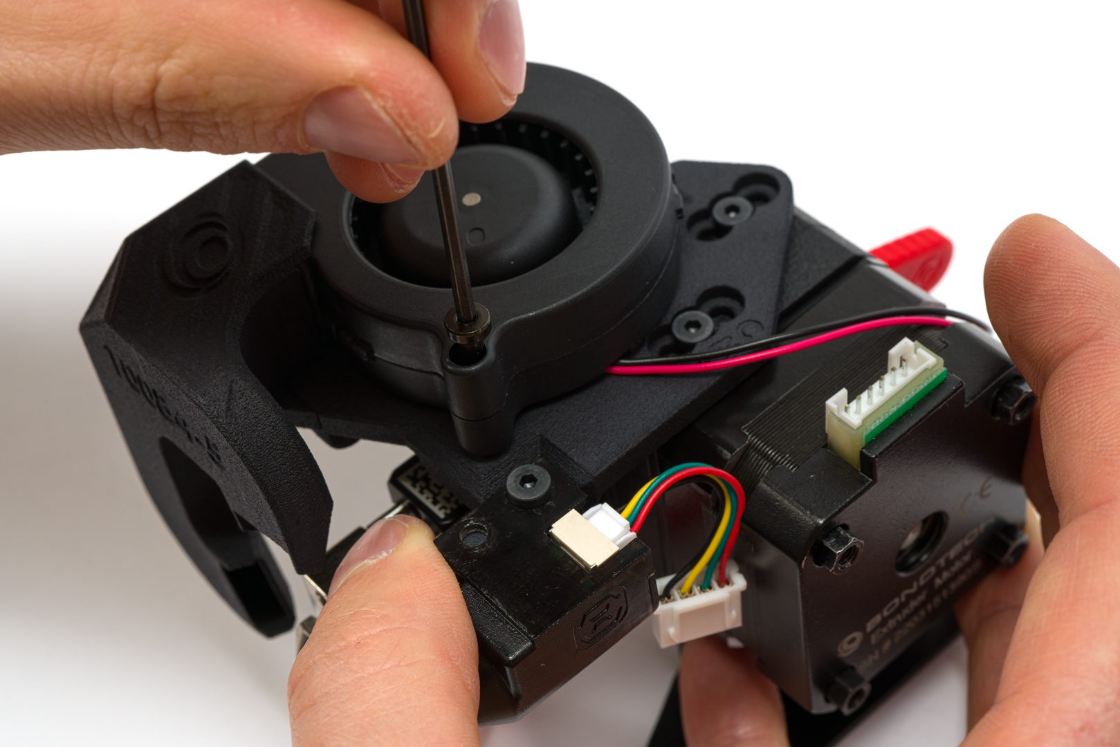
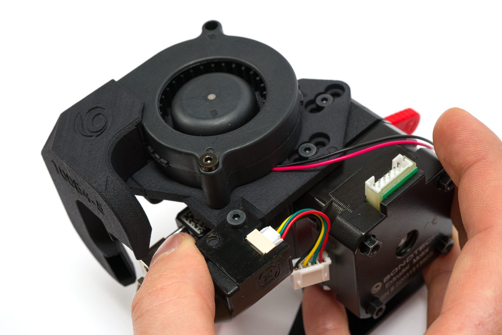
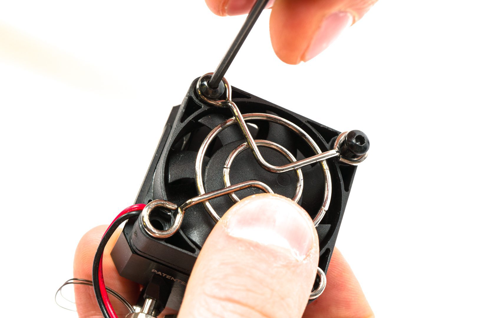
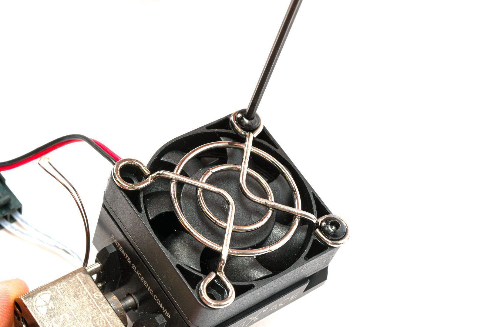
Step 4.8 Install the Mosquito Fan
Take the assembly so far and Mosquito 25mm fan and its 2 mounting screws
Place the fan in place aligning the top holes with the Mosquito heat sink holes
Tighten the screws, but not too much
When your LGX for Artillery includes the GX ACE Magnum+, use the stock axial fan
Use the stock axial fan
Tighten it to the heat sink
Using both stock screws
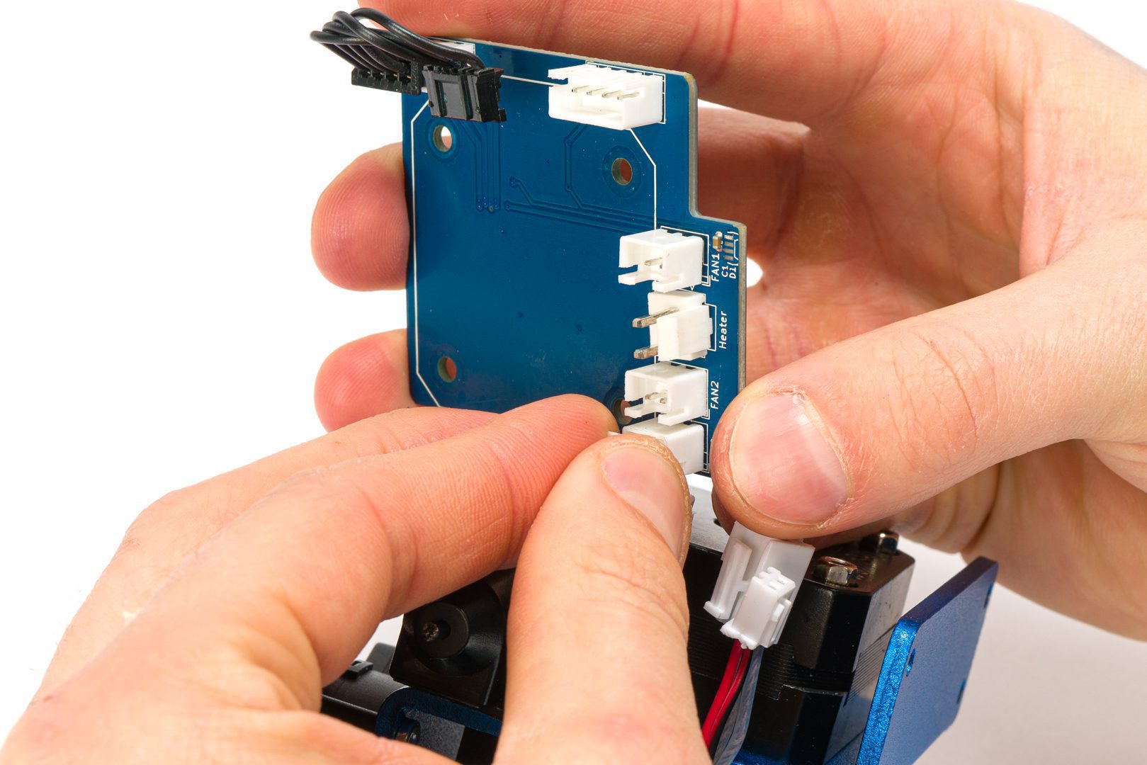
Step 4.9 Connect the breakout board
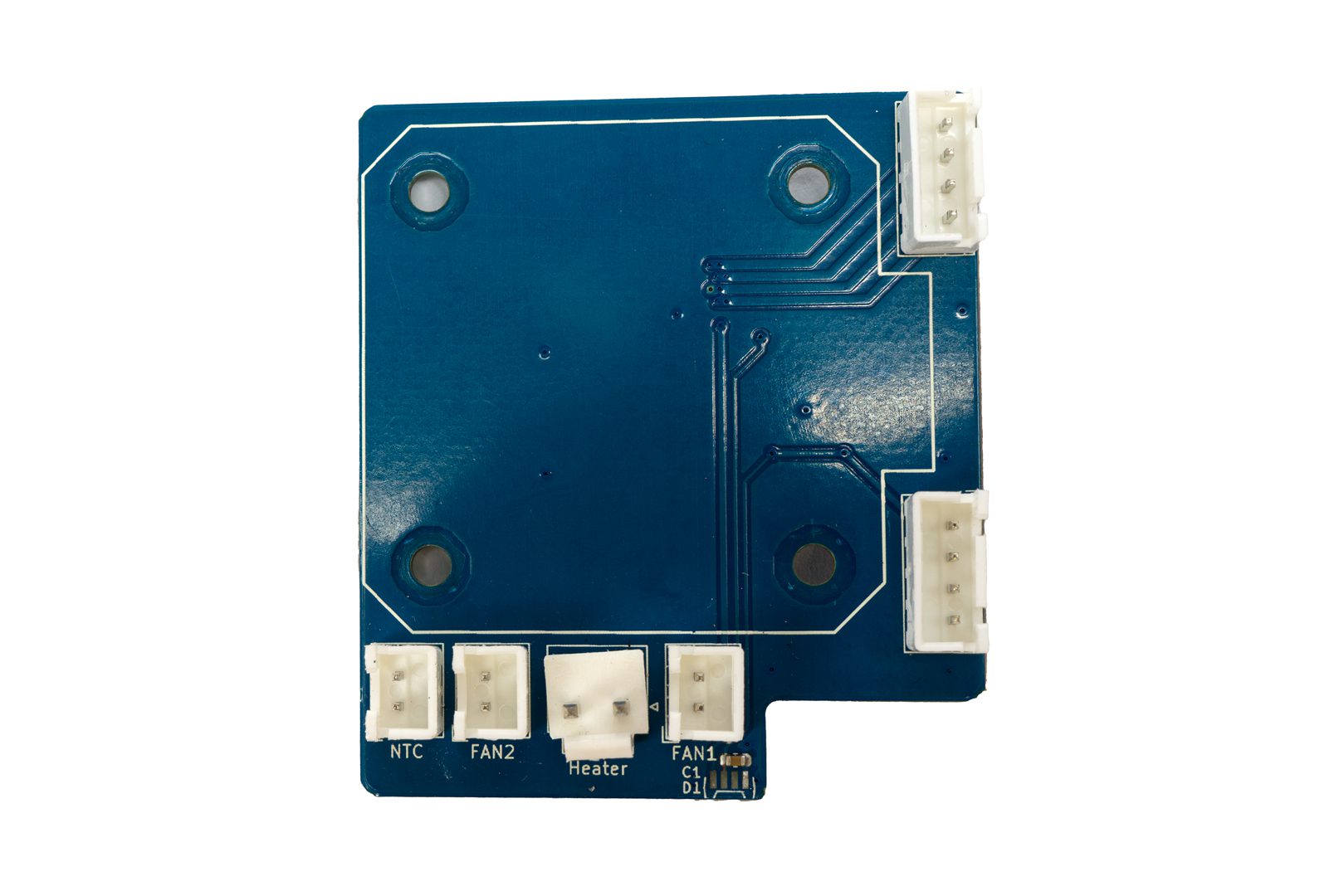
Take the stock breakout board and notice the connector labels
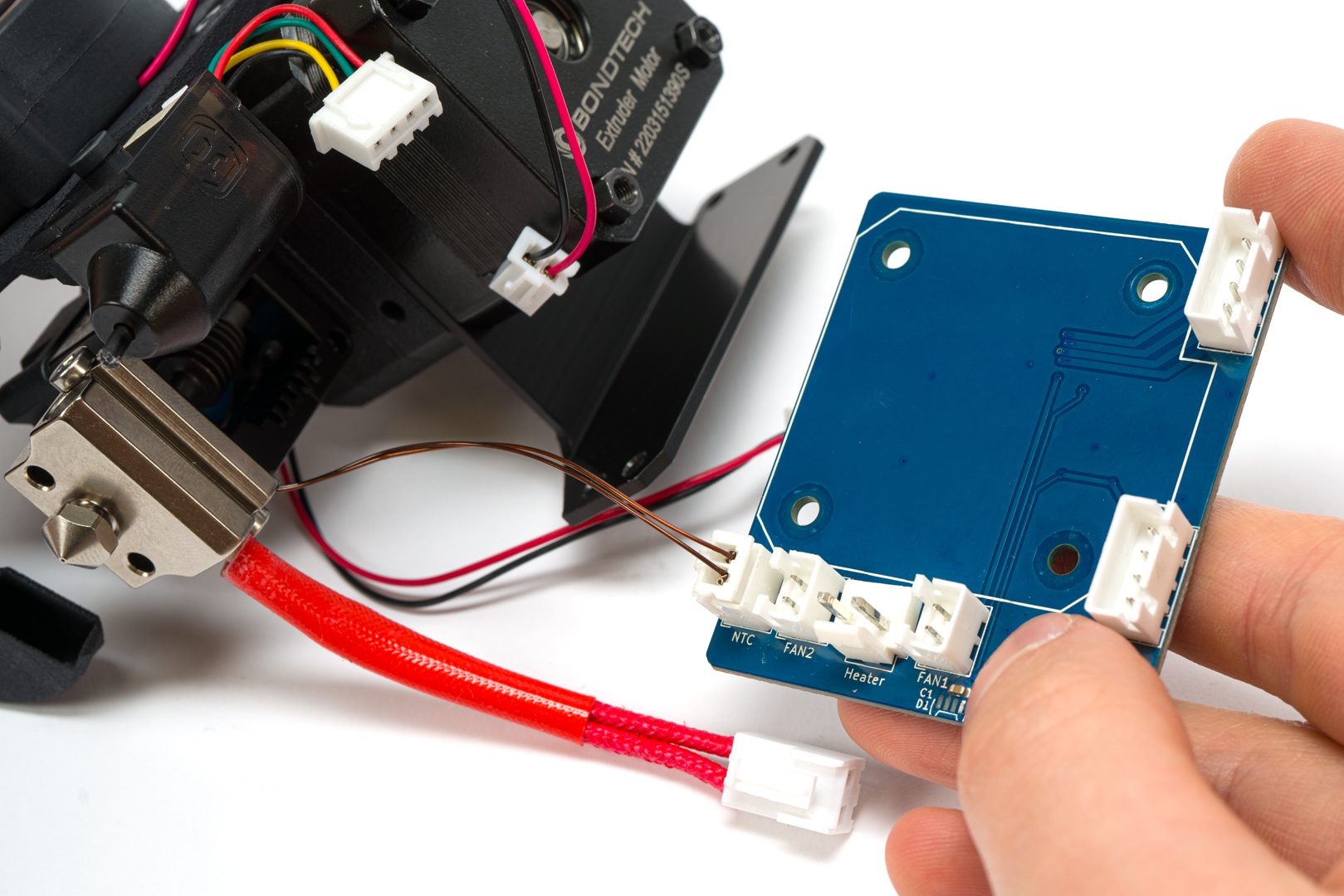
Connect the thermistor
Connect the hotend fan
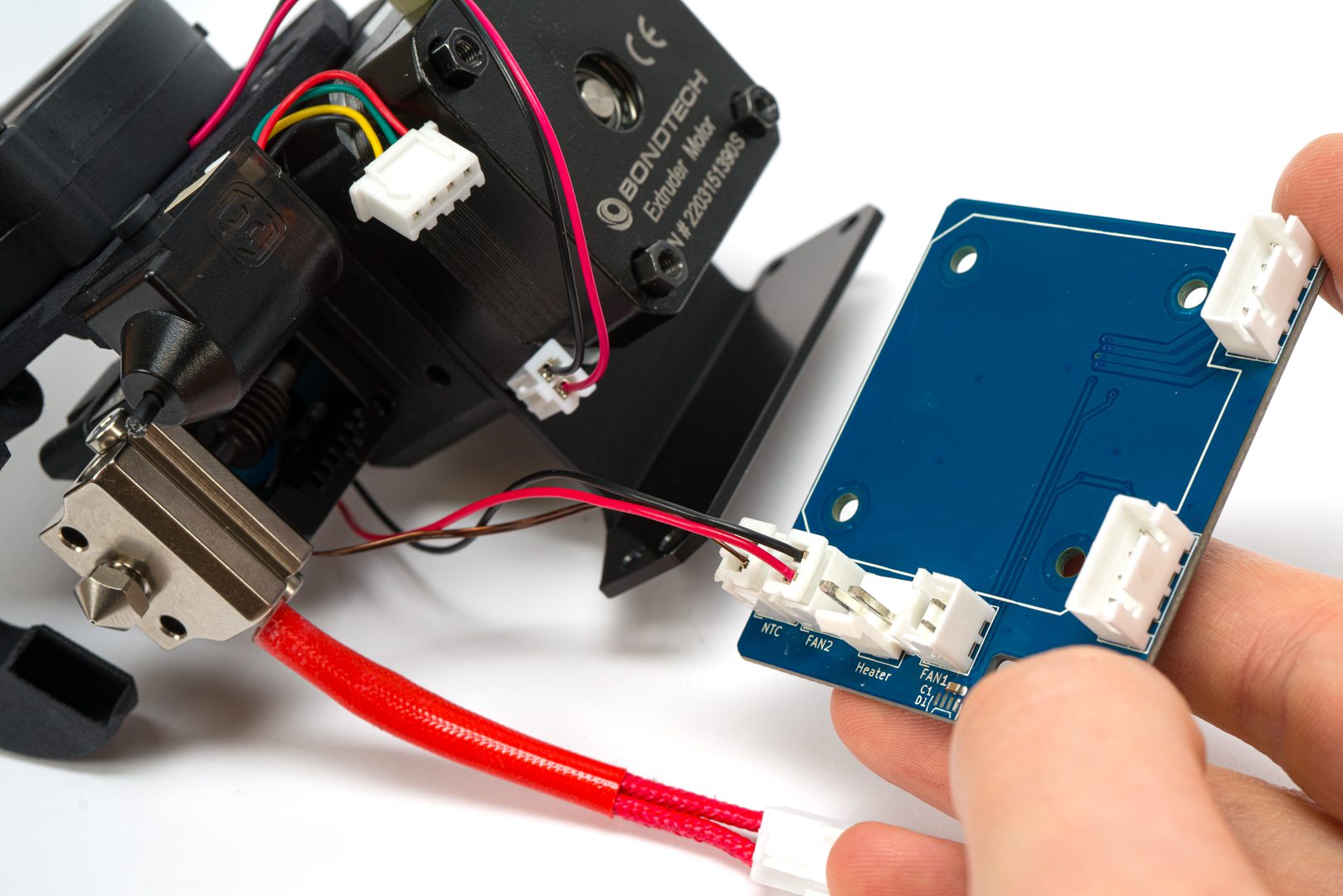
Connect the heater
Connect the part cooling fan
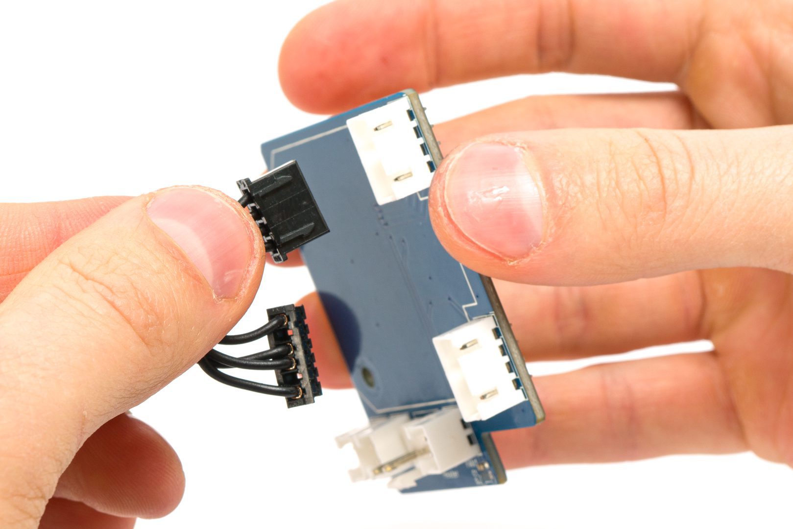
Orient the breakout board towards the back of the LGX
Connect the stepper motor cable
Step 4.10 Install the breakout board
Use the 2 stock breakout board screws and a 2.0mm hex key
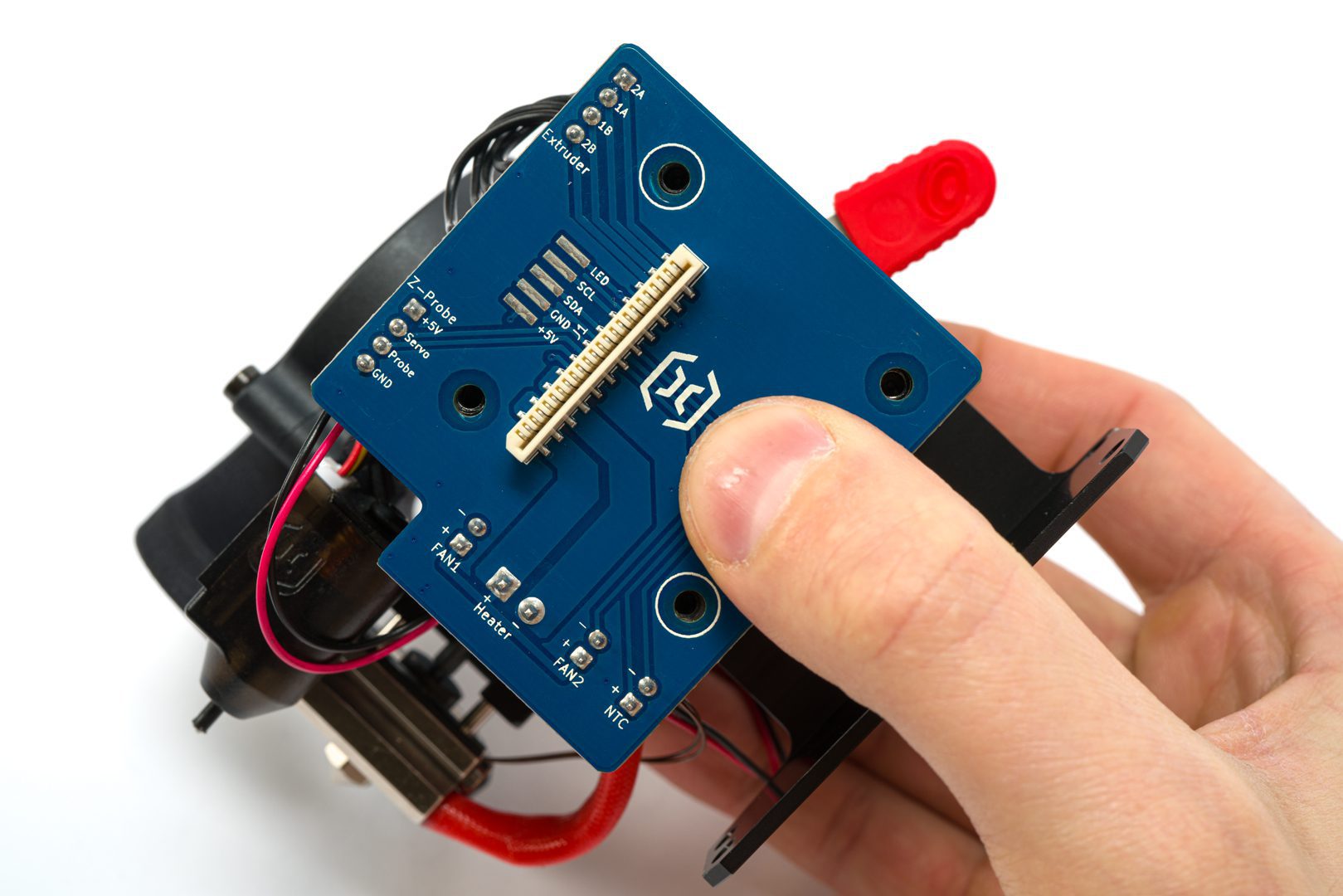
Align the board with 2 of the LGX studs following this orientation
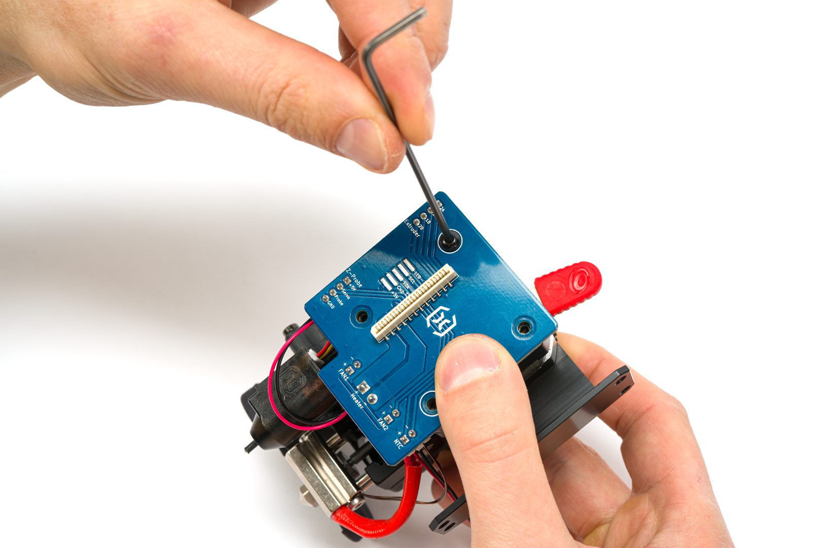
Screw it in place using both screws
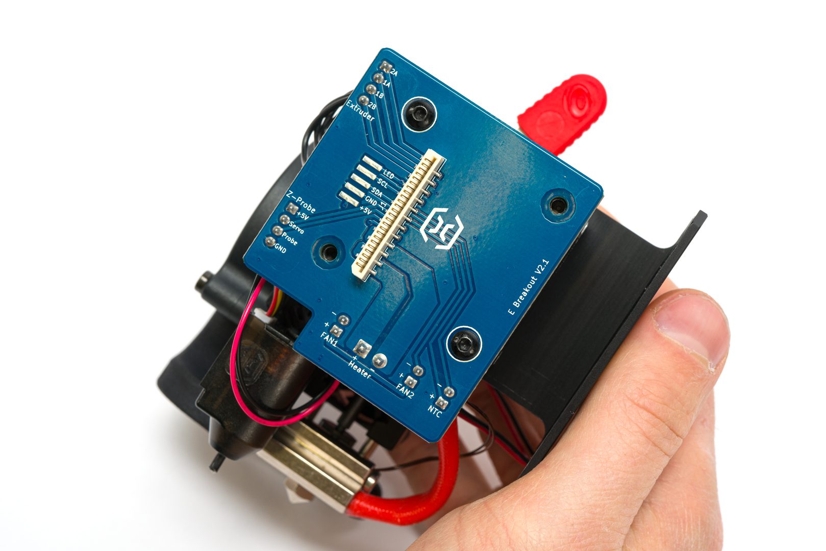
Check the alignment and orientation
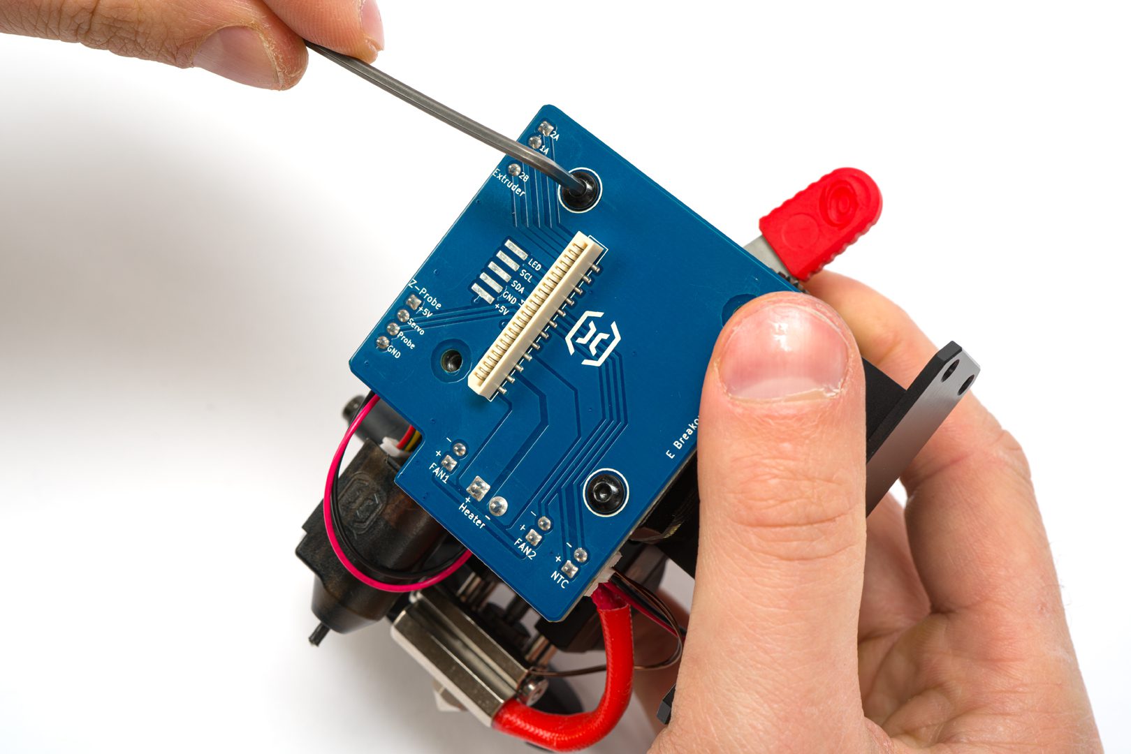
Tighten the screws to prevent the breakout board to wiggle
Finishing Up The Mechanical Installation
You 've asembled your LGX for Artillery Set. Now it's time to install it on your Artillery.
These are the following steps to finish up the mechanical installation:
- Use 3x M3x6 Low head screws to secure the LGX Printhead to the X-carriage on the same position as stock. Install all 3 screws and tighten it after you set the extruder vertical.
- If your printer has the loose LED chip, now it’s time to put it back.
- Install back the Breakout board cover
- Hide excessive cables behind the cover
- Carefully insert the ribbon cable
- If you use ribbon cable securer, put it back in place.
Step 4.11 Attaching ALU mount to x-carriage plate
Use 3 M3x6mm screws to hold the ALU mount onto the x-carriage
Top right holding point
Bottom holding point
Top left holding point
Step 4.12 Installing breakout board cover
If your printer has the loose LED chip, now it’s time to put it back.
Insert a breakout board cover screw in the top right hole and align it with the top right LGX stud
Secure the cover by tightening the screw onto the stud
Insert the second screw and tighten both
Step 4.13 Re-connecting the flat cable
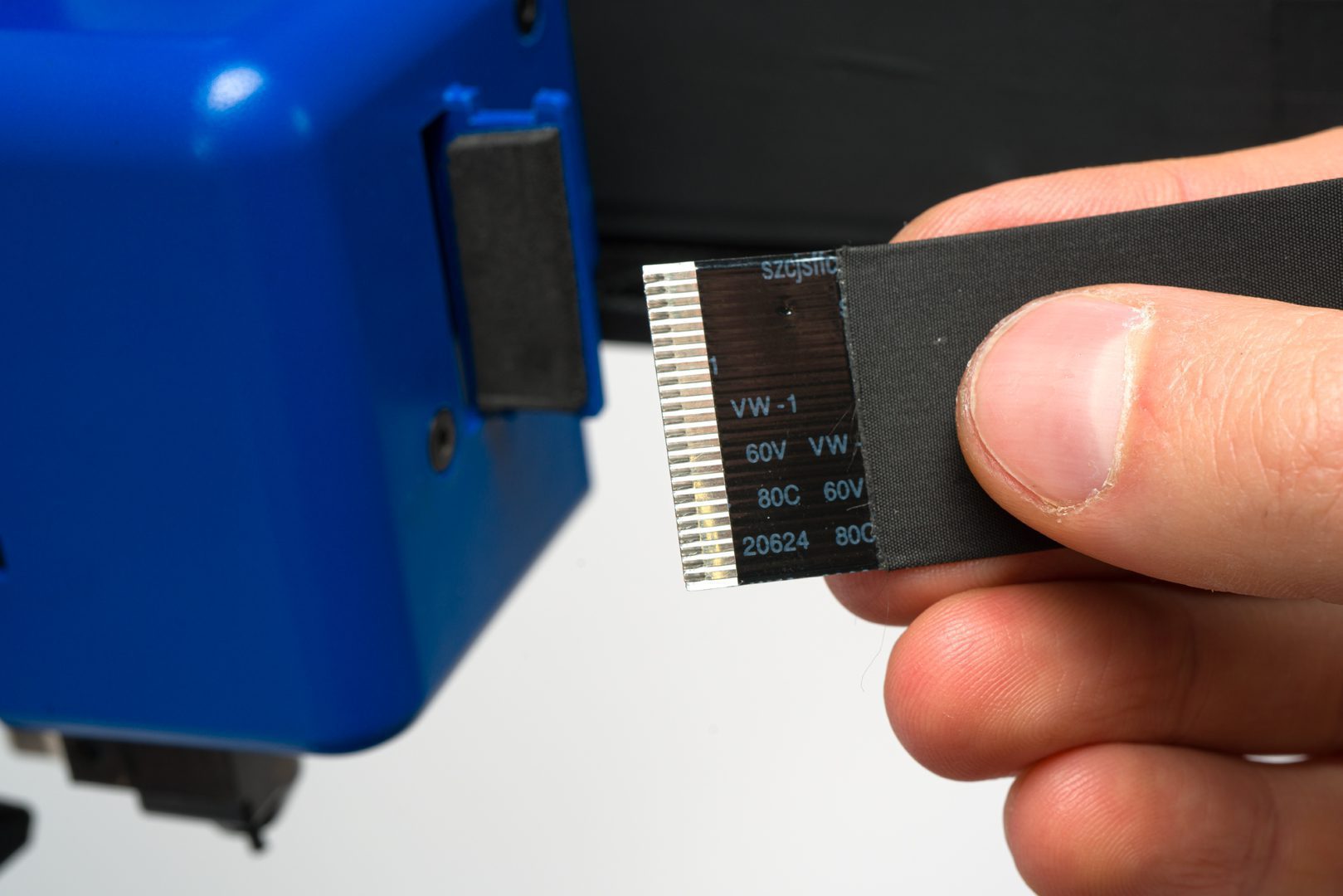
The flat cover will connect to the breakout board plug
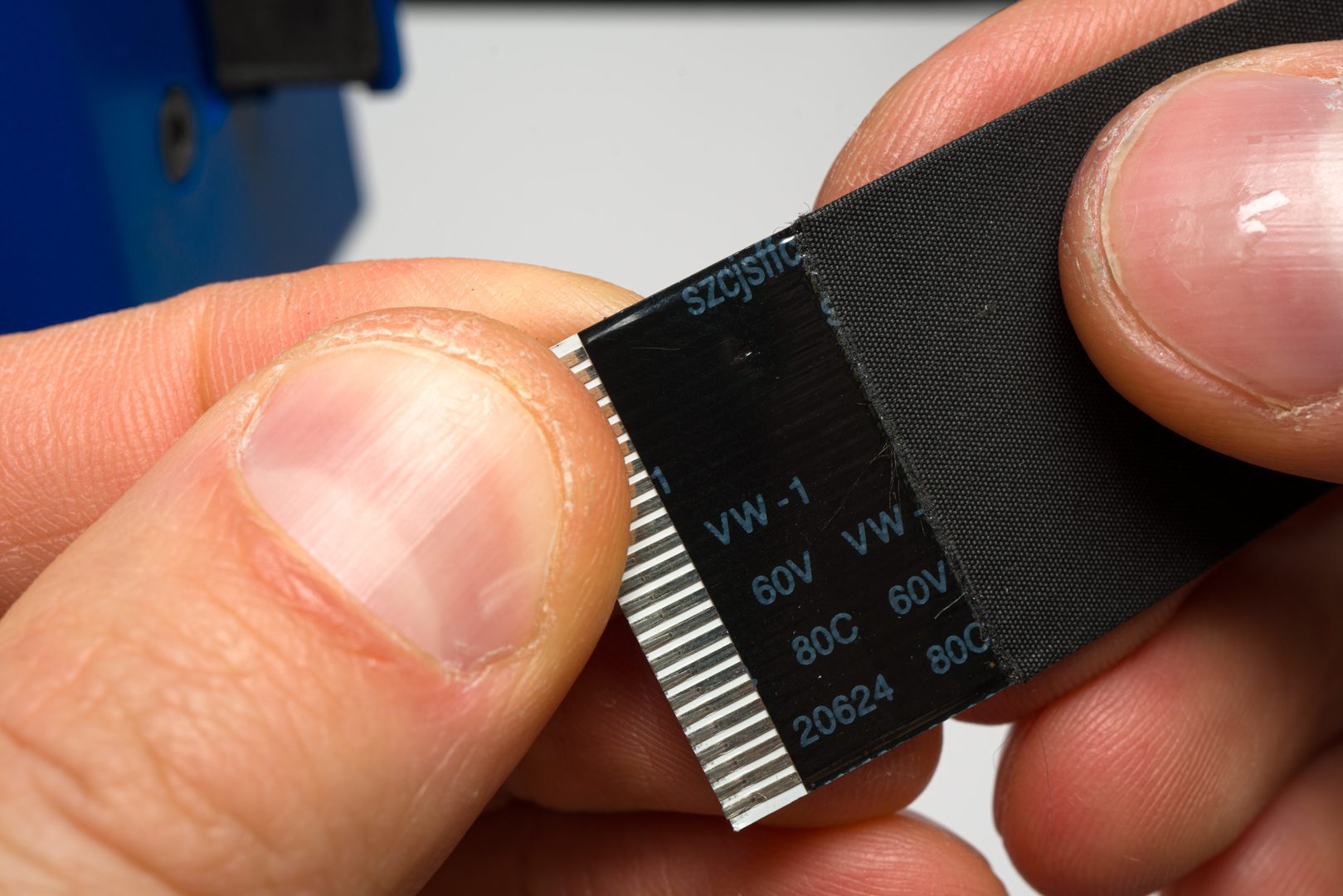
Mind the vertical orientation of the pins
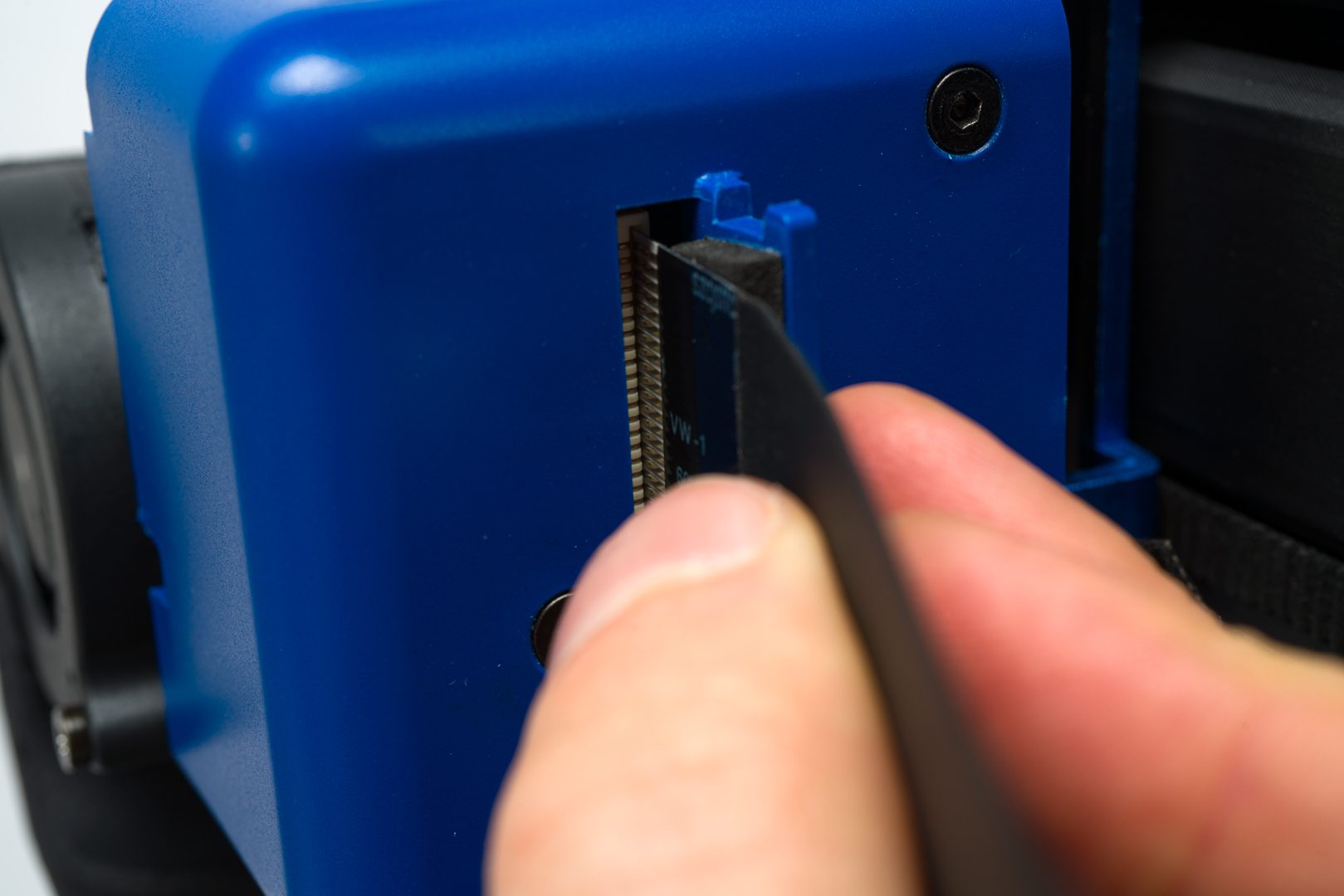
Plug the cable in
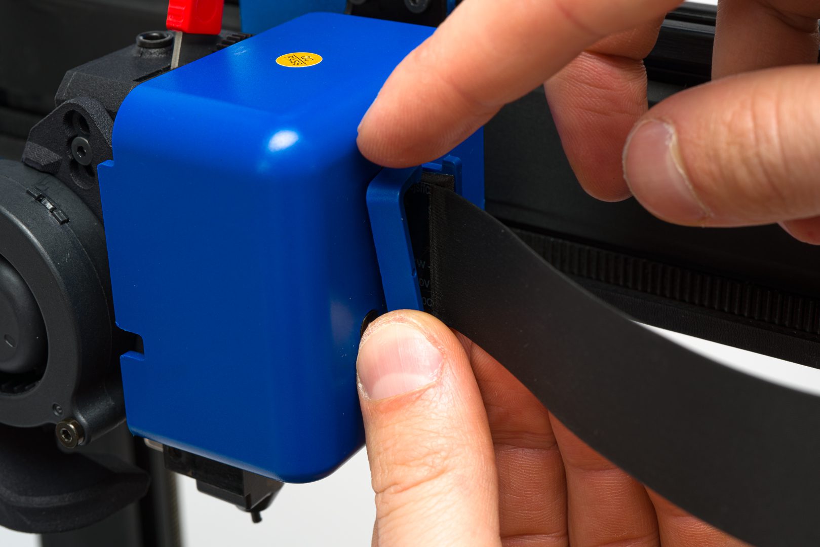
Position the cable clip back in place
Make sure it stays aligned and in position
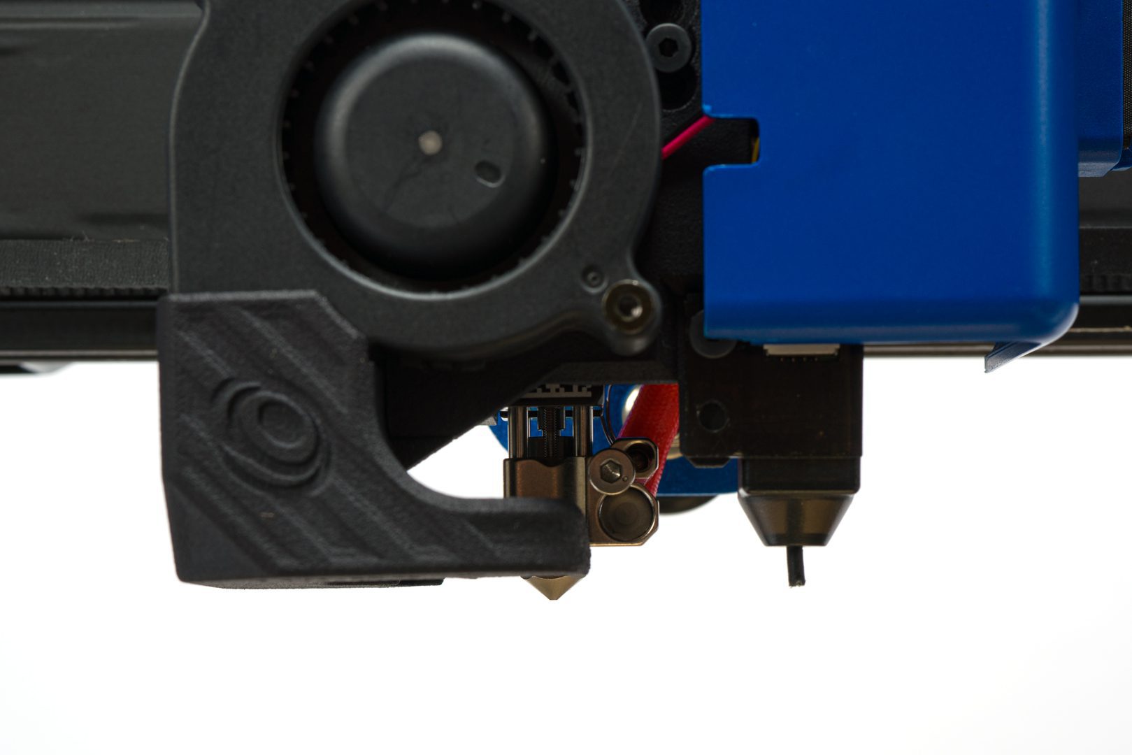
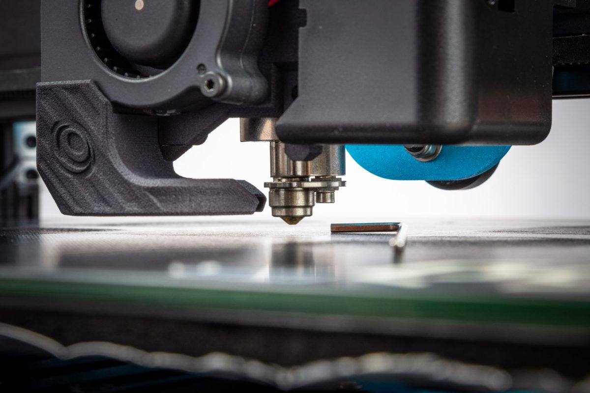
Check the position of the levelling probe is slightly above the nozzle tip
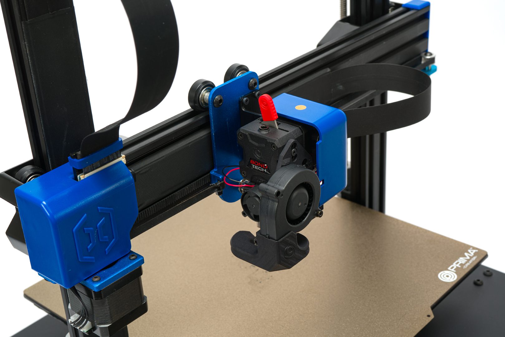
The LGX for Artillery is installed!
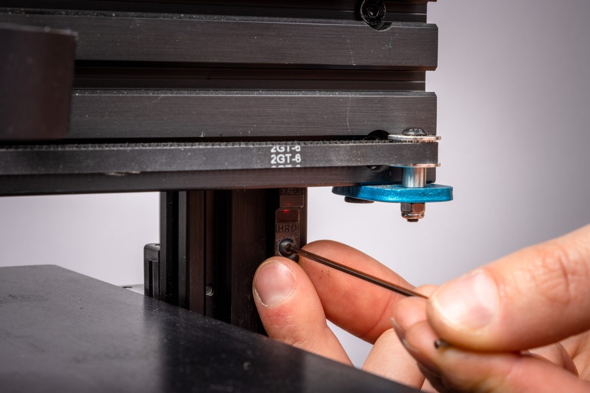
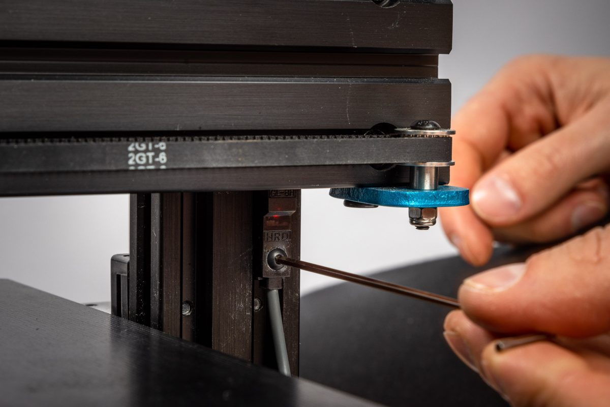
Step 5.1 Prepare 3D printer to be used with the LGX upgrade kit
FOR MODELS WITHOUT BED LEVELLING SENSOR
Have the printer powered on with steppers disabled while doing this step.
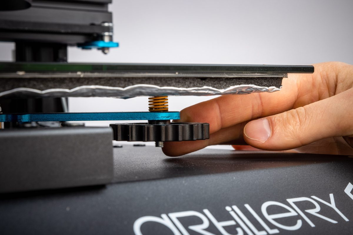
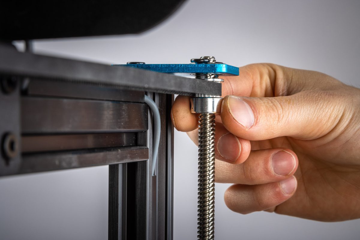
Lower the bed with the 4 bed levling knobs/screws under the bed and place as low as possible. Do not force the screws, just lower the bed until it is in the bottom.
Place the printhead in the center of the buildplate and rotate the Z-screws so the nozzle is just above the bed, use a 2.0mm hex key for reference.
Use a 2.0mm hex key and remove the Z-endstop sensor screw
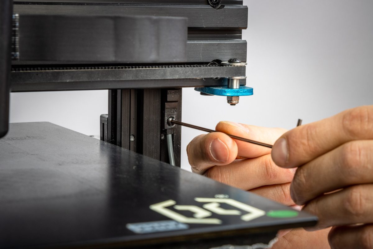
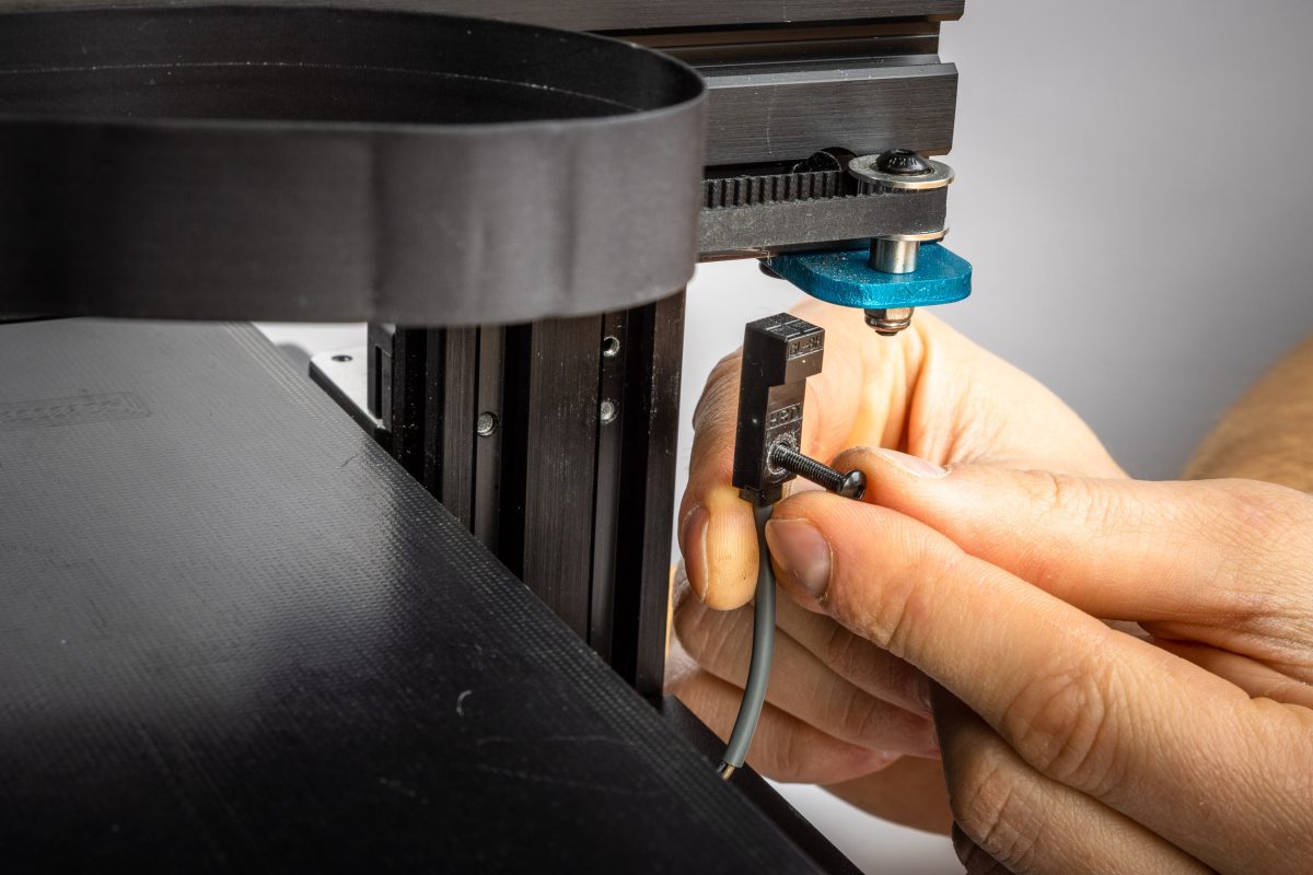
use the M3x10 screw and the M3 T-nut that comes with the kit and install it into the sensor
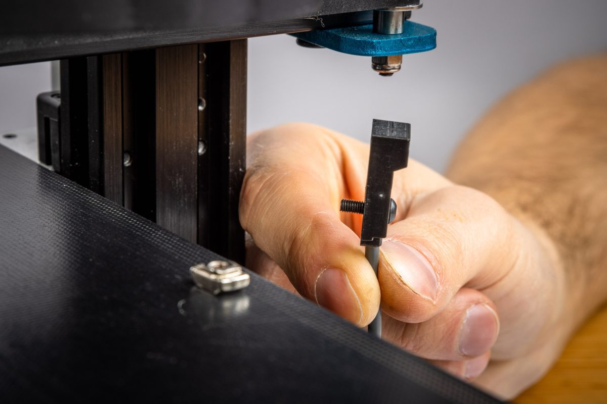

Install the sensor to the frame and place it in a position so the sensor barely triggers (light up with a red led or touch depending on what sensor is used) as low as possible from the X frame. Secure the sensor when you find the right spot, it could be good to tighten loose, adjust up or down until you find the right spot. Tighten but not too hard while you have it in the right place.
If the sensor does not get secure to the frame with the T-nut, unscrew the screw a bit and then tighten it again.
LEVEL THE BED
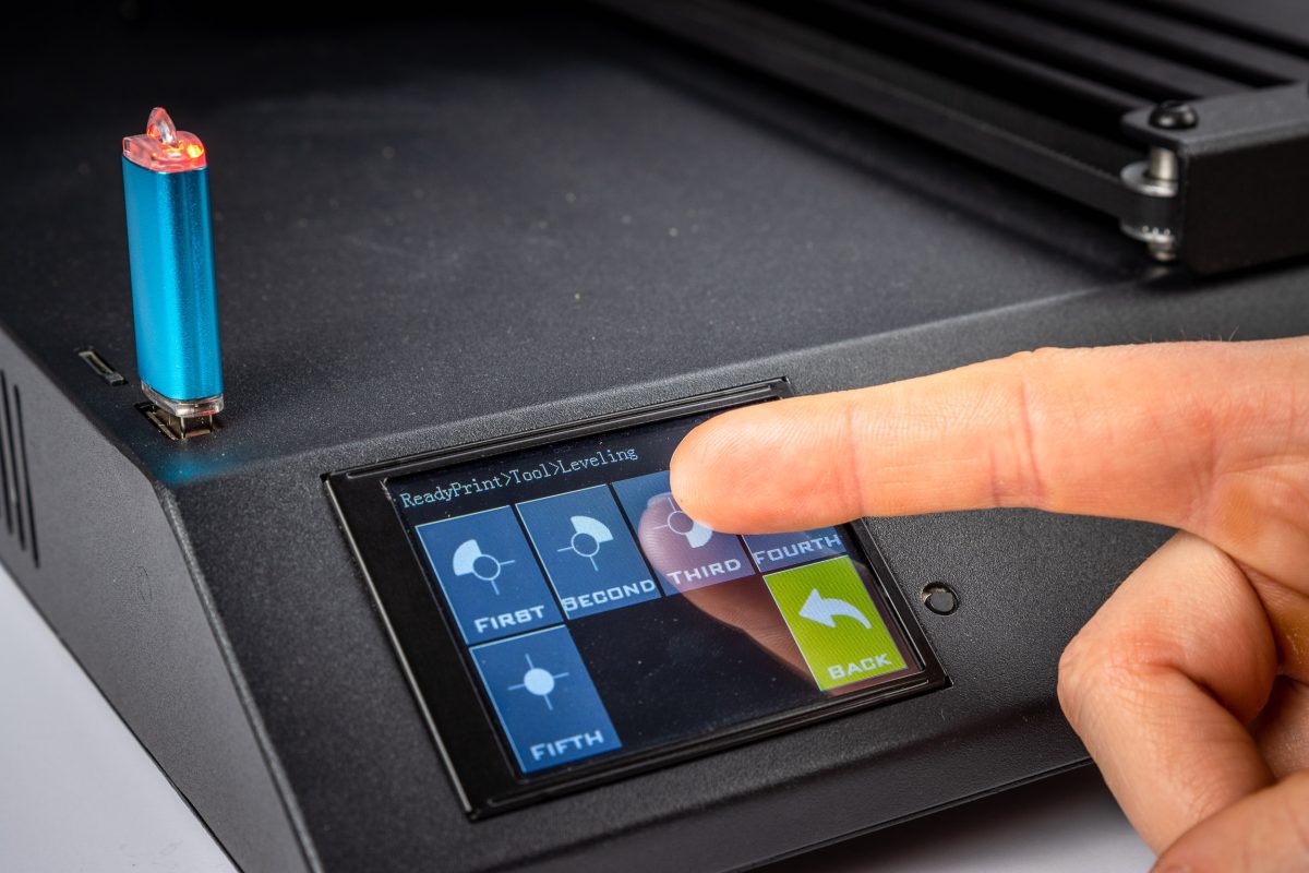
Perform the Bed Leveling sequence. In the printer menu, go to
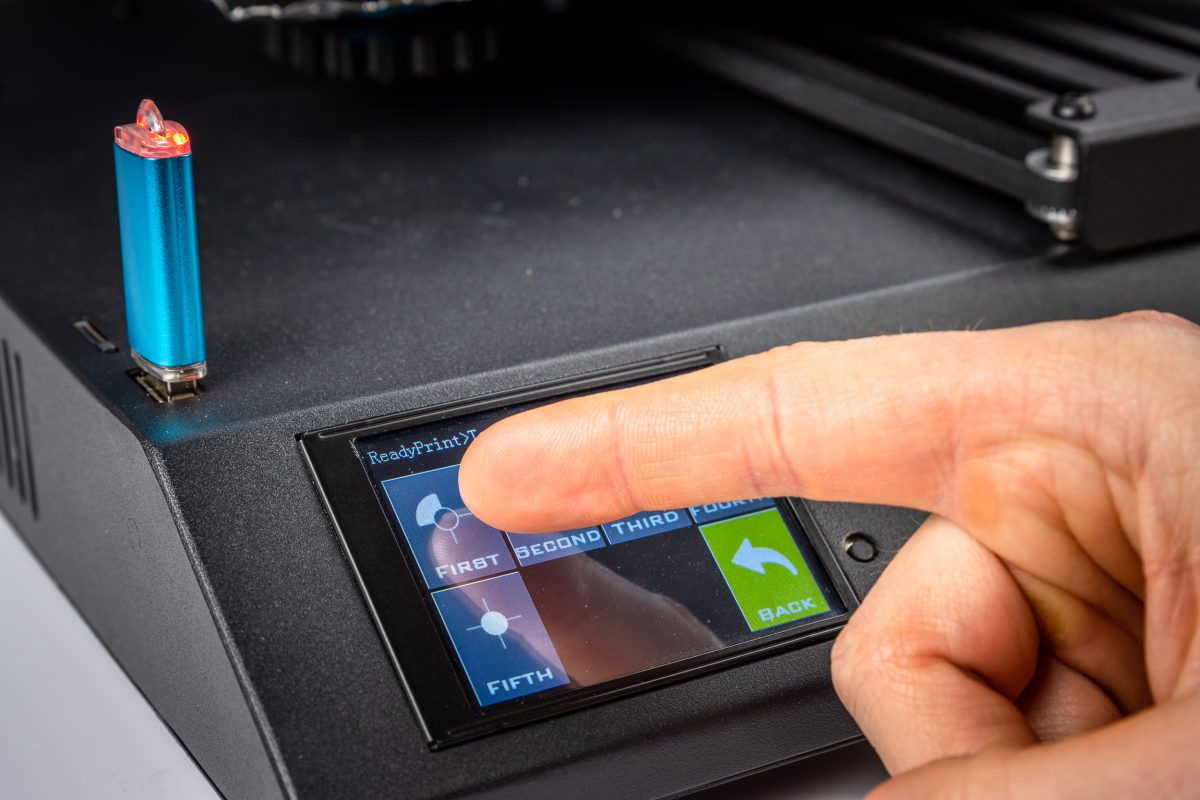
TOOLS > LEVEL
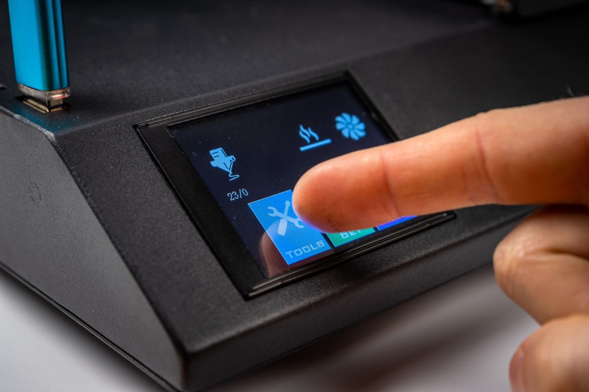
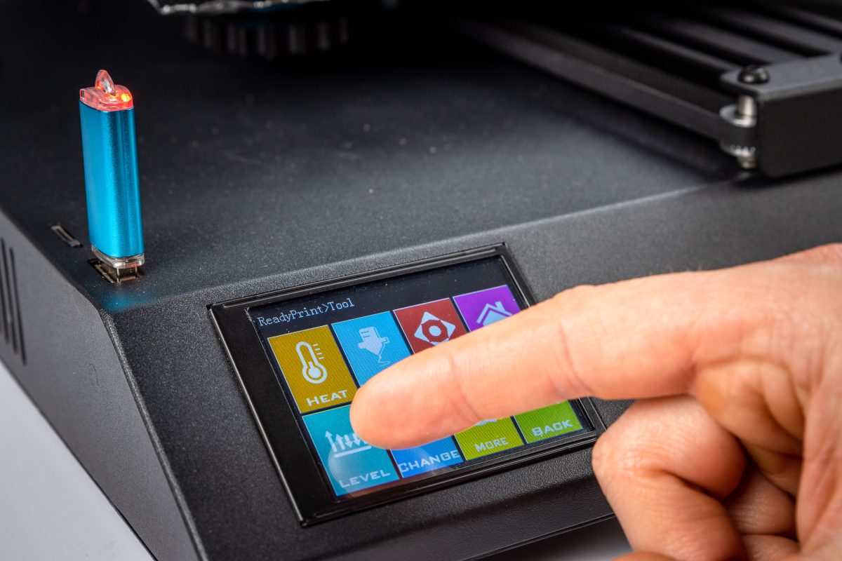
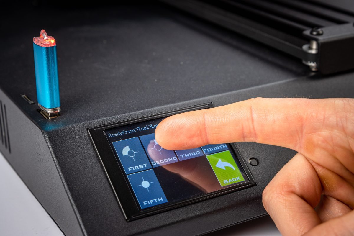
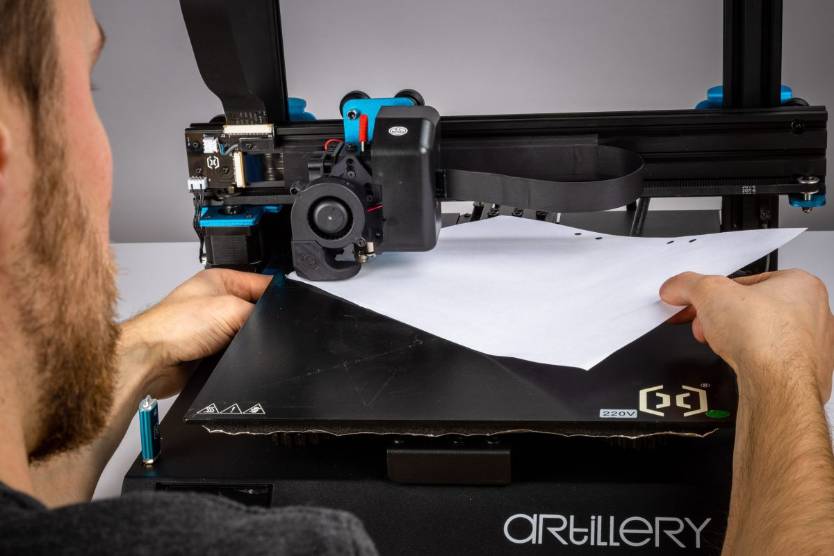
In the LEVEL menu, press FIRST. When the printer have moved to the first position, use a paper and move the paper side to side when you raise the bed. when you feel a slight resistance on the paper, you are in the right height.
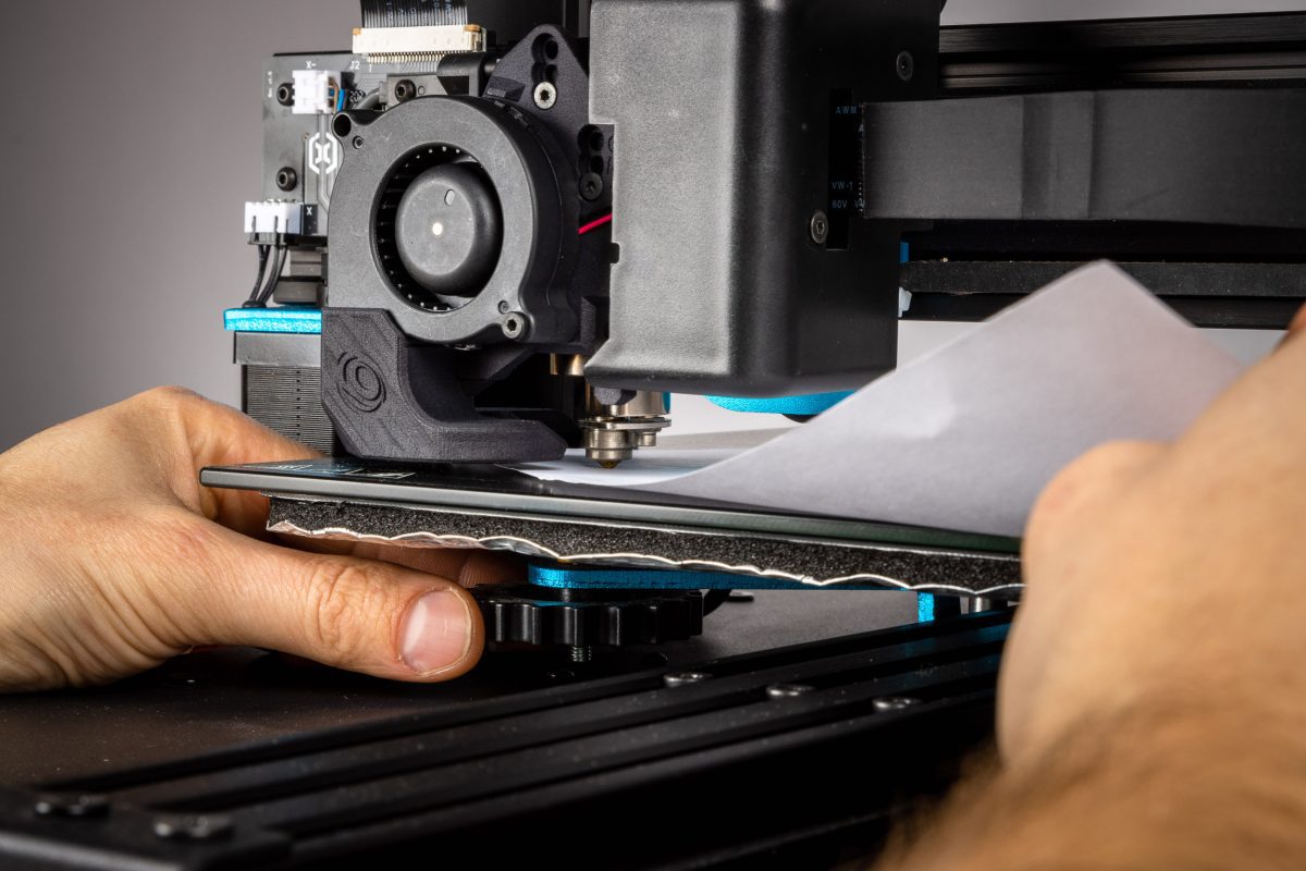
Continue with all 4 corners, repeat at least 1 time
For printer without bed leveling sensor, If the bed can't go high enough to level the bed, lower the bed to the bottom again, then lower the Z-endstop 1-2mm and try the Bed Leveling Sequence again.
ADJUST STEPPER MOTOR CURRENT :
- Use a multimeter and set the multimeter to read Voltage DC;
- On the mainboard, turn the extruder Stepper driver potentiometer counterclockwise 1/4 turn, be very careful to not touch any other component;
- Measure the negative input (with the black end) on the main board negative input and the potentiometer as positive end (red);
- You may need to lower the sensitivity on the multimeter tool to get the correct reading, it should be set to 0.5-0.6V, adjust the potentiometer further if needed.
Step 5.2 Slicer Settings and e-steps value
ADD TO START GCODE :
- Open the slicer software you use;
- Select your Artillery 3D printer upgraded with LGX;
- Access its machine settings;
- Edit the start g-code;
- Add the following command to the top of the code:
M92 E400; sets e-steps value for LGX extruder
M500; save settings to EEPROM
SLICER SETTINGS :
- Adjust retraction speed to be between 25-40mm/s;
- Adjust retraction distance to be the same as yout nozzle diameter,e.g. 0.4mm when using a 0.4mm nozzle;
SILICONE BOOT :
With this Bondtech LGX Kit, you will get a 5015 part cooling fan. It is much stronger than stock. It is recommended to use a silicone boot for the hotend.
If the part cooling fan is cooling the hot block too much, the hotend may not have power to keep up the temperature. If you don't have the silicone boot, you may also lower the cooling percentage on the slicer settings of your profiles.
Print Profiles
3D Print Recomendations
… coming soon …
3D PRint Profiles
… coming soon …
Only logged in customers who have purchased this product may leave a review.
Related products
Reviews
There are no reviews yet.