


LGX Shortcut Copperhead for AnyCubic Mega
The budget option
for Home users and starting Makers.Main Advantages
- Use all available nozzle temperatures without compromise;
- Master abrasive, rigid, flexible and soft filaments;
- Far better part cooling;
- Clean, simple and easy to install;
- Improves extrusion’s reliability and resolution;
- Compatible with Anycubic Mega-X, Mega-S and Mega-P(ro);
Price:
$287.38
Only 4 left in stock (can be backordered)
Select Currency
Select Country
LGX Shortcut Copperhead for Anycubic Mega-X, Mega-S and Mega-P(ro)
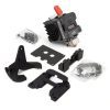
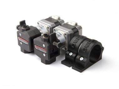
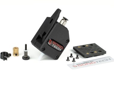
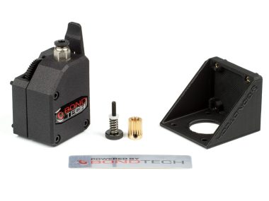
This Upgrade Kit includes the following items:
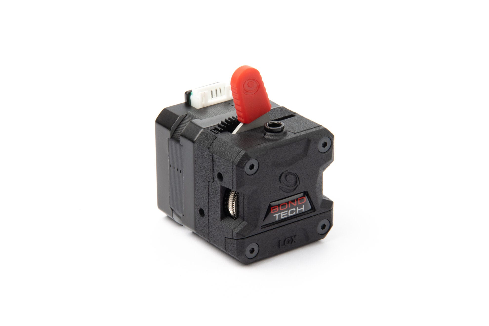
- LGX extruder;
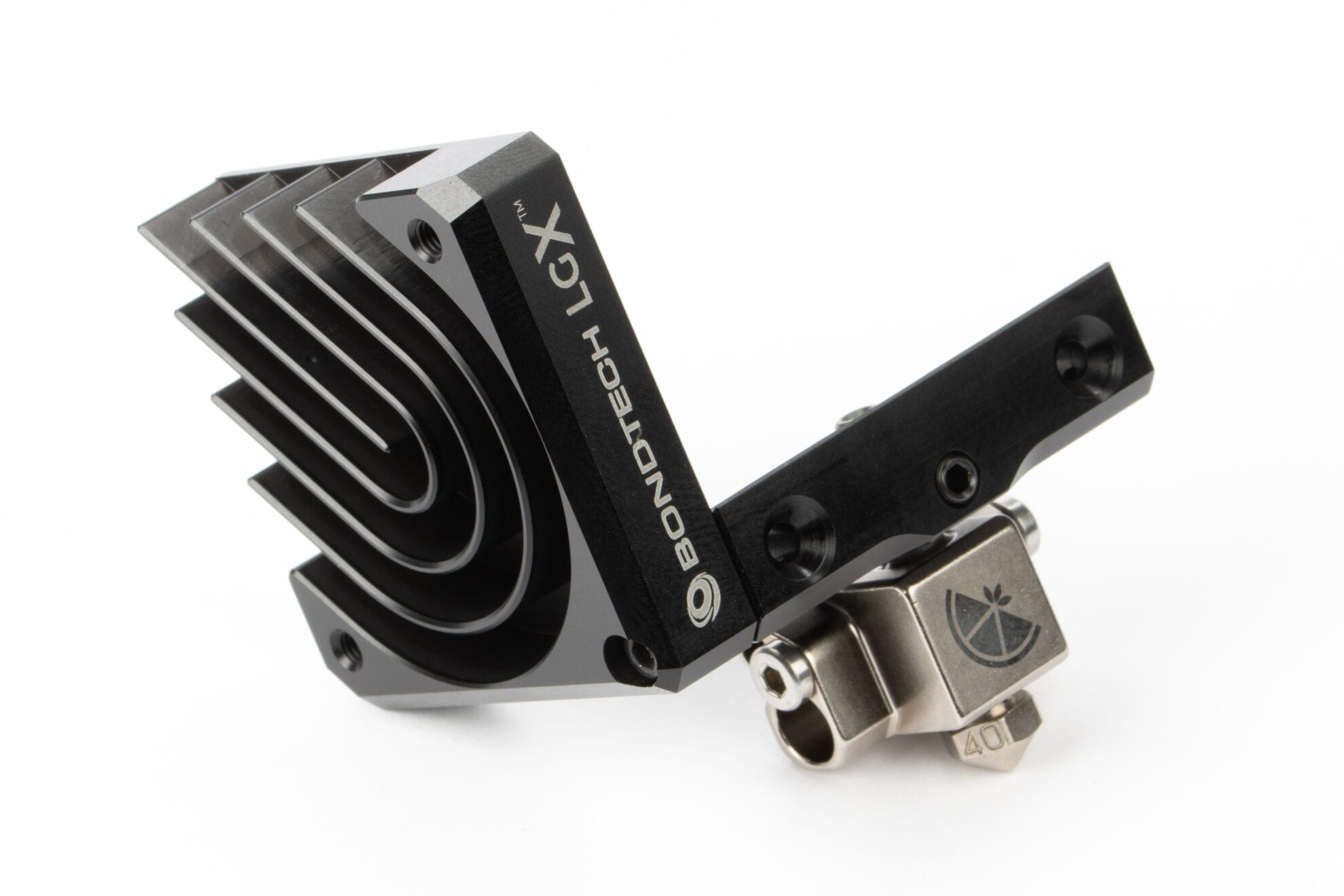
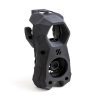
- LGX Shortcut Copperhead hotend;
- LGX Shortcut Accessories for Anycubic Mega.
Abrasive filaments
To use abrasive materials with this Upgrade Kit you need nozzles for abrasive materials:
| Freight Weight | 520 g |
|---|---|
| Dimensions | 21.5 × 8 × 10.5 cm |
Print Parameters
You may 3D print with the Bondtech LGX Shortcut on your Anycubic using a generic profile, with the exception of the 2 settings described below.
Adjust the e-steps value
Add the following command to the beginning of the Start G-code:
M92 E400
Locate the Start G-code on the profile you use for your Anycubic on your slicer.
Adjust Retraction Distance
Change the Retraction Distance setting to:
0.6mm
Locate the Retraction Distance under Print Settings on the profile you use for your Anycubic on your slicer.
SETUP GUIDE
Setting Up the Bondtech LGX Shortcut Upgrade Kit for Anycubic
This guide shows how to install the Bondtech LGX Shortcut Upgrade Kit on Anycubic Mega-X, Mega-S and Mega-P(ro).
The whole process is divided into 5 stages. Click each tab to reveal the steps on each stage. This guide assumes you know how to operate your 3D printer. If you don’t, please refer to Anycubic’s Documentation.
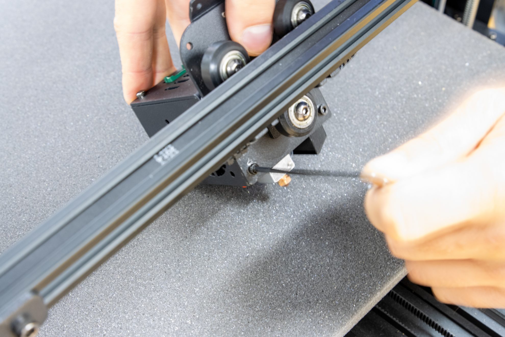
Step 1. Unload Filament

Protect the print bed

Command filament unloading

Release the stock extruder and unload filament.
Step 2. Set the printer OFF

Let the printer cool down.

Raise the X-gantry 45mm along the Z-axis.

Turn the printer OFF and disconnect the power cable.
Step 3. Release PTFE and Main Cable

Cut the main cable zip ties.

Unplug the main cable from the print head.

Remove the PTFE tube from the push-fit.
Step 4. Release Printhead From Carriage
If you have a Mega-S or Mega-P(ro)
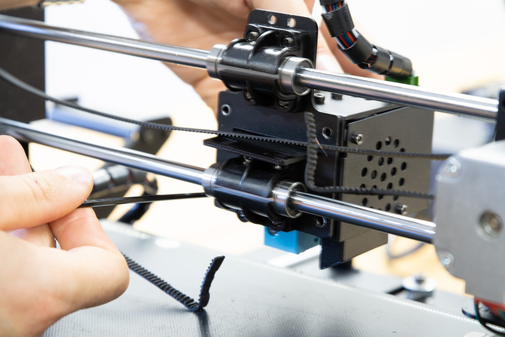
The Mega-S and Mega-P use a different method to hold the x-axis belt and to move the x-carriage.
You need to cut the zip ties that hold the belt.
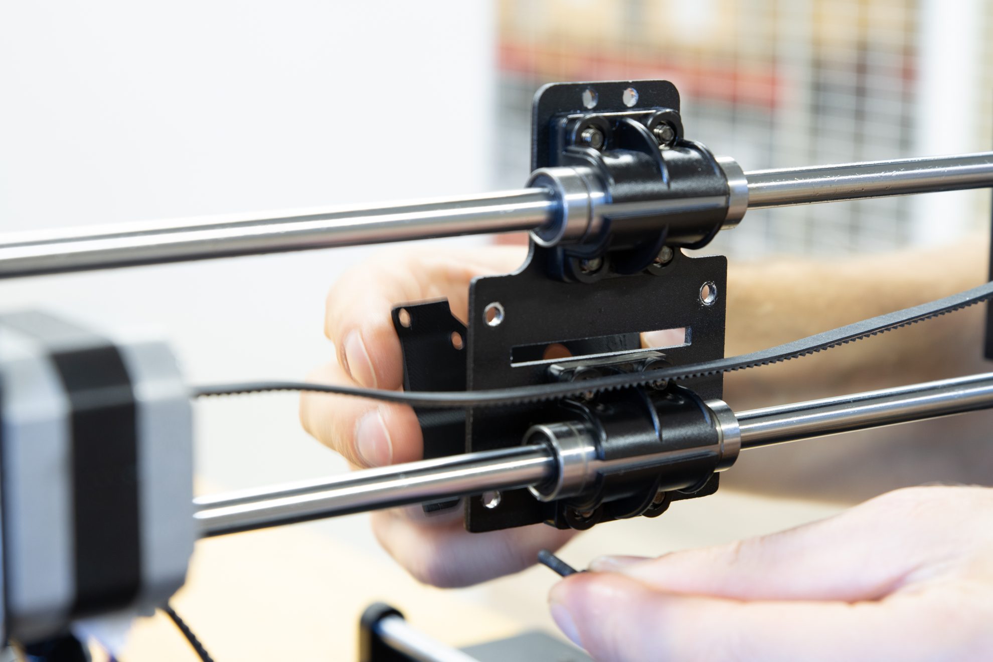
Then you can release the print head from the sliding x-carriage by unscrewing the screws on the pictures from the rear.
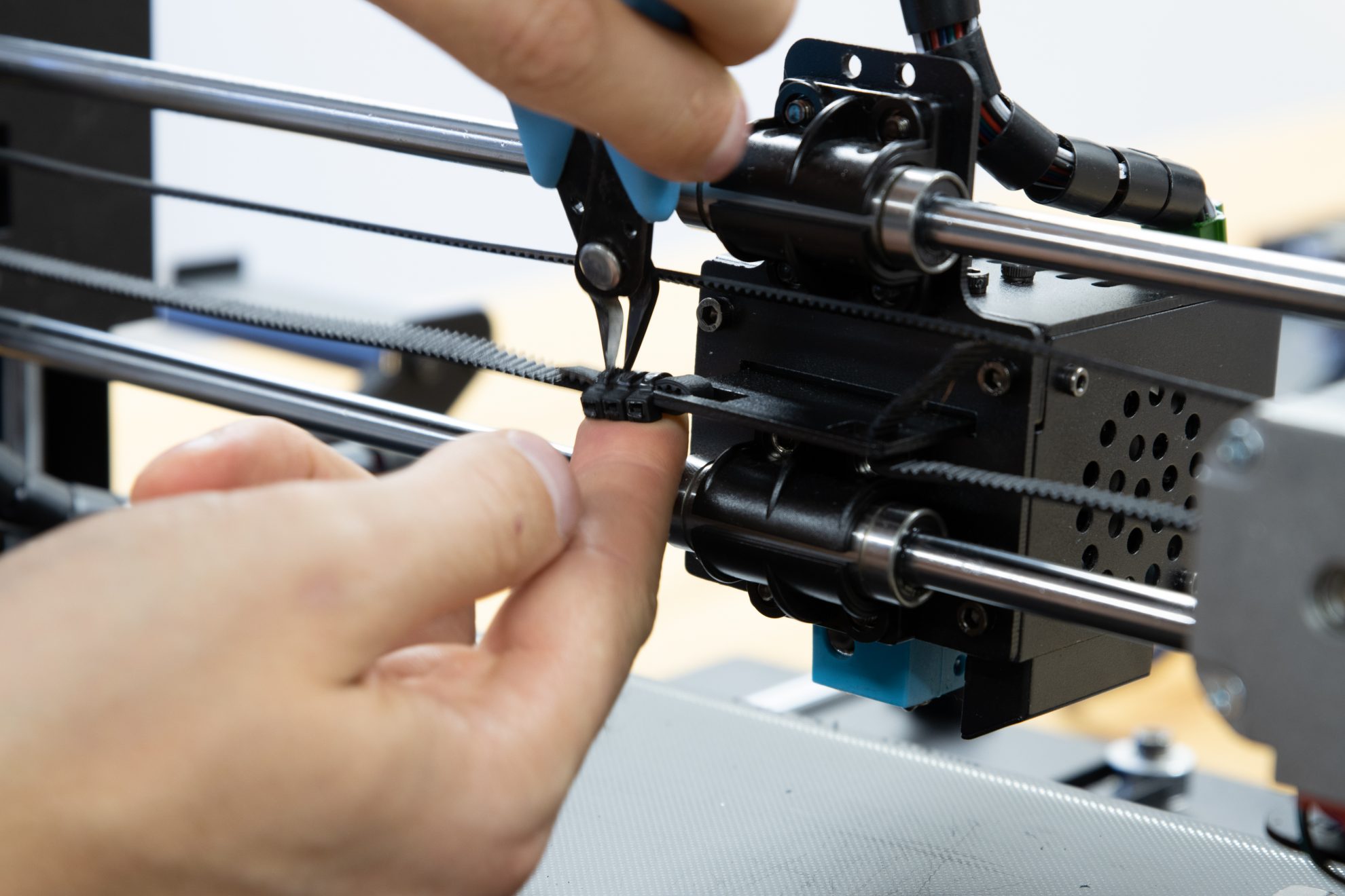
Cut the zip ties
holding the belt...

... and release the belt
from the carriage.

Unscrew this screw
at the rear of the x-carriage...
... and the other 3 screws
holding the print-head.

Remove this screw that attaches the printhead to the x-carriage.
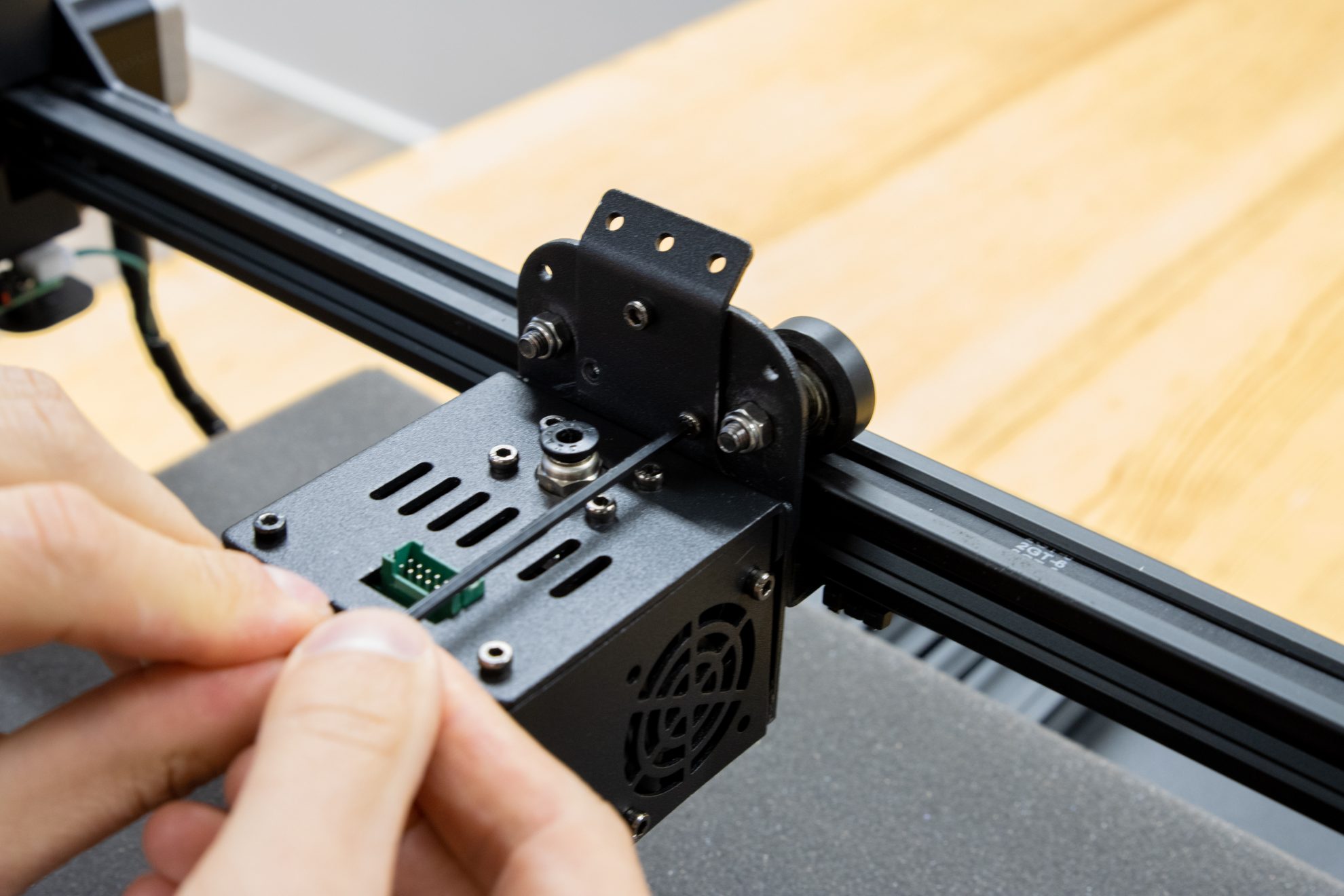
Remove this screw as well.

Use a 8mm wrench to grab the x-carriage wheels' nut...

... and a 3.0 mm hex key to loosen the carriage wheel.

Loosen the other wheel as well.
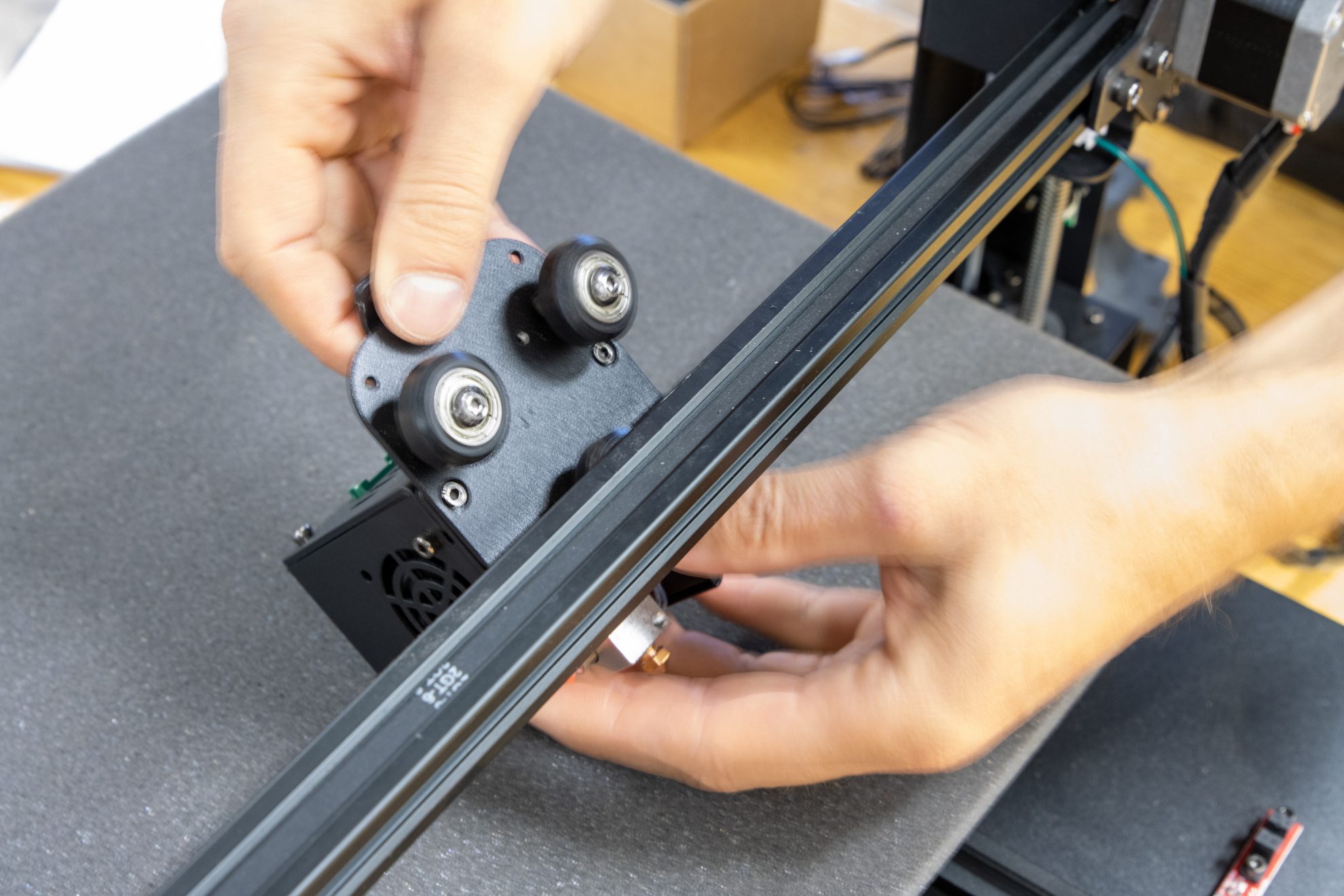
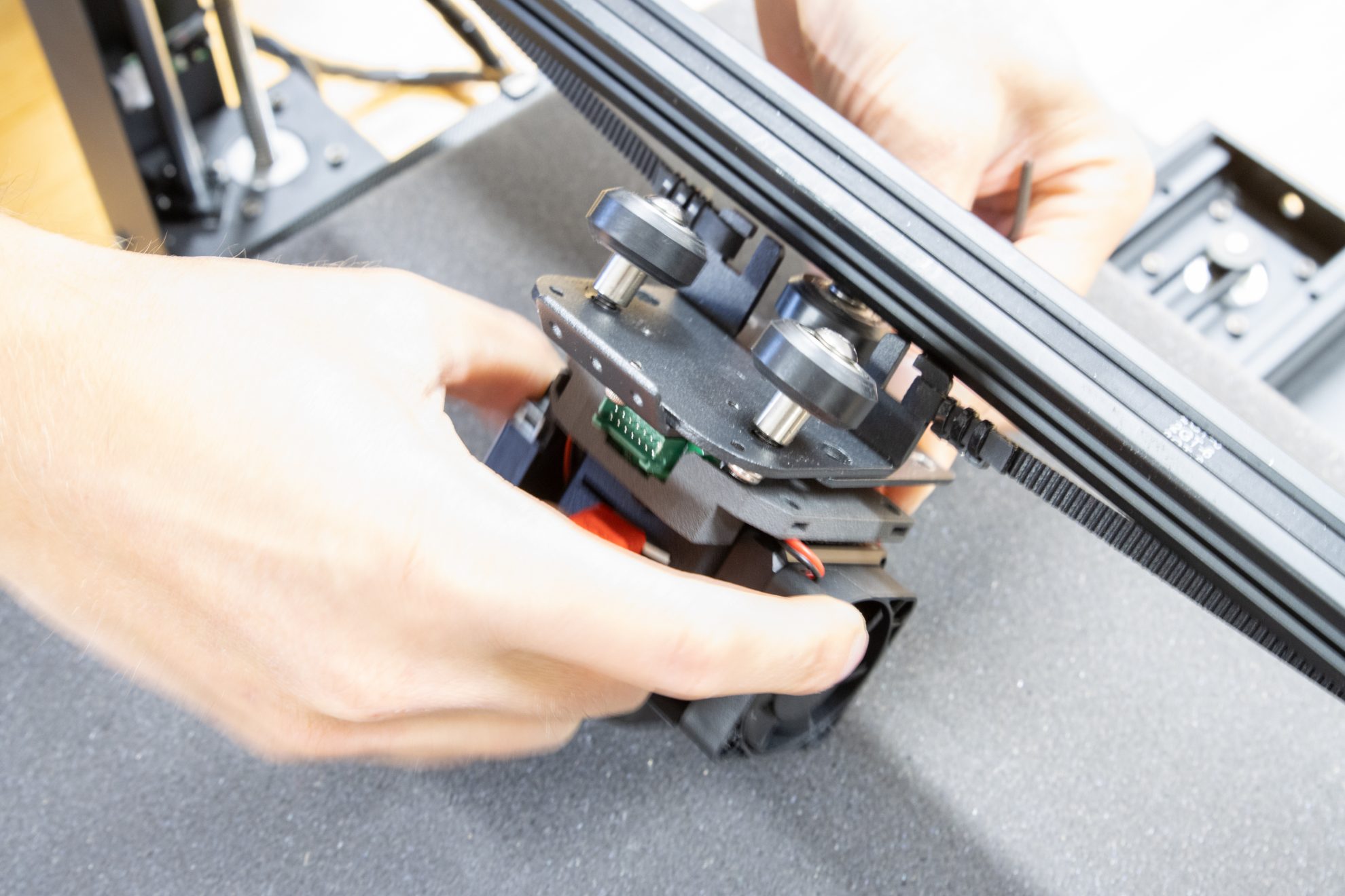
Remove the x-carriage from the x-axis profile.
Remove this screw.

Remove this screw.
Step 5. Release the print head assembly from the x-carriage

Remove this screw.

Remove this screw.

Detach the print head from the x-carriage plate.
Step 6. Disassemble the print head

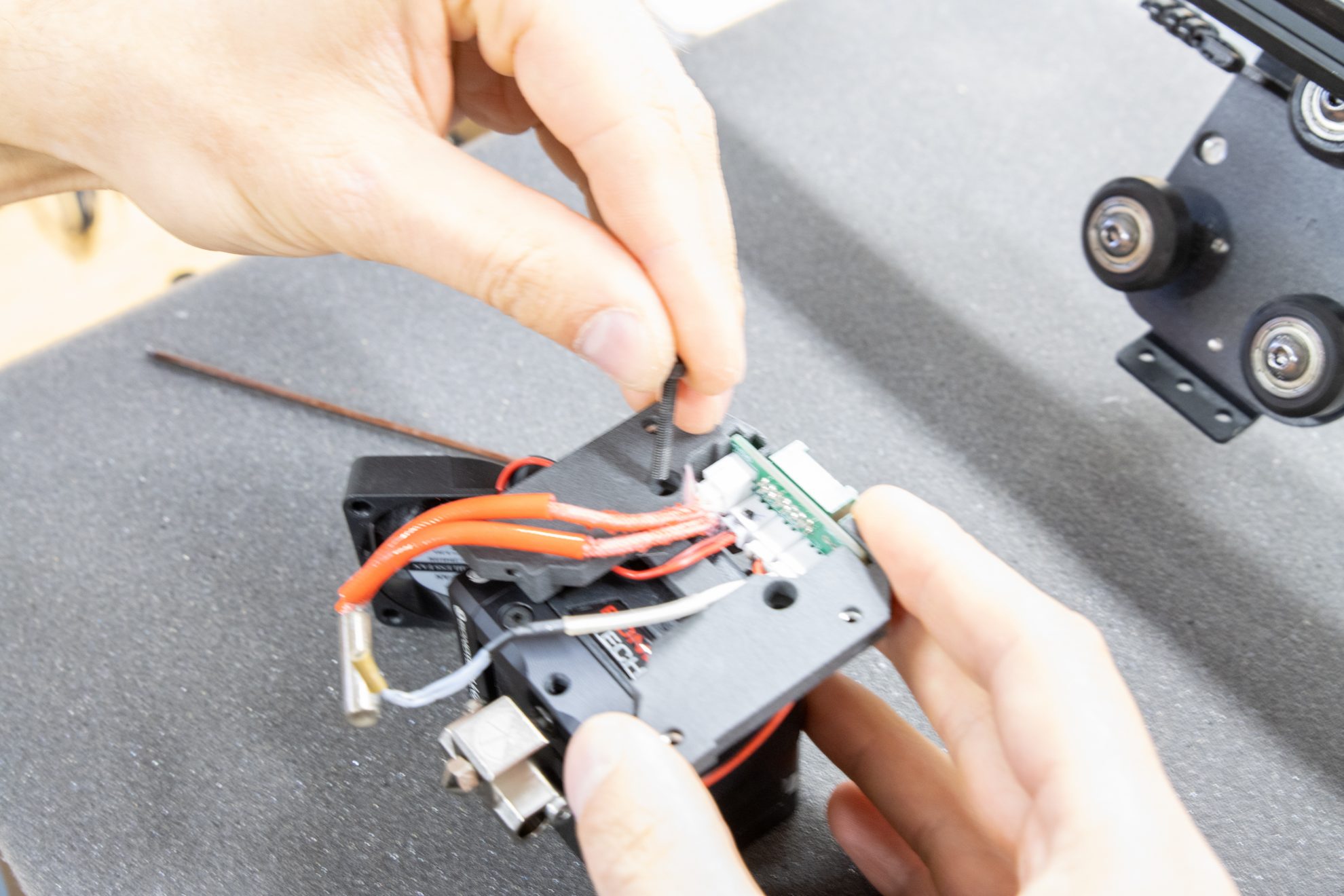
Remove this screw.

Remove this screw.
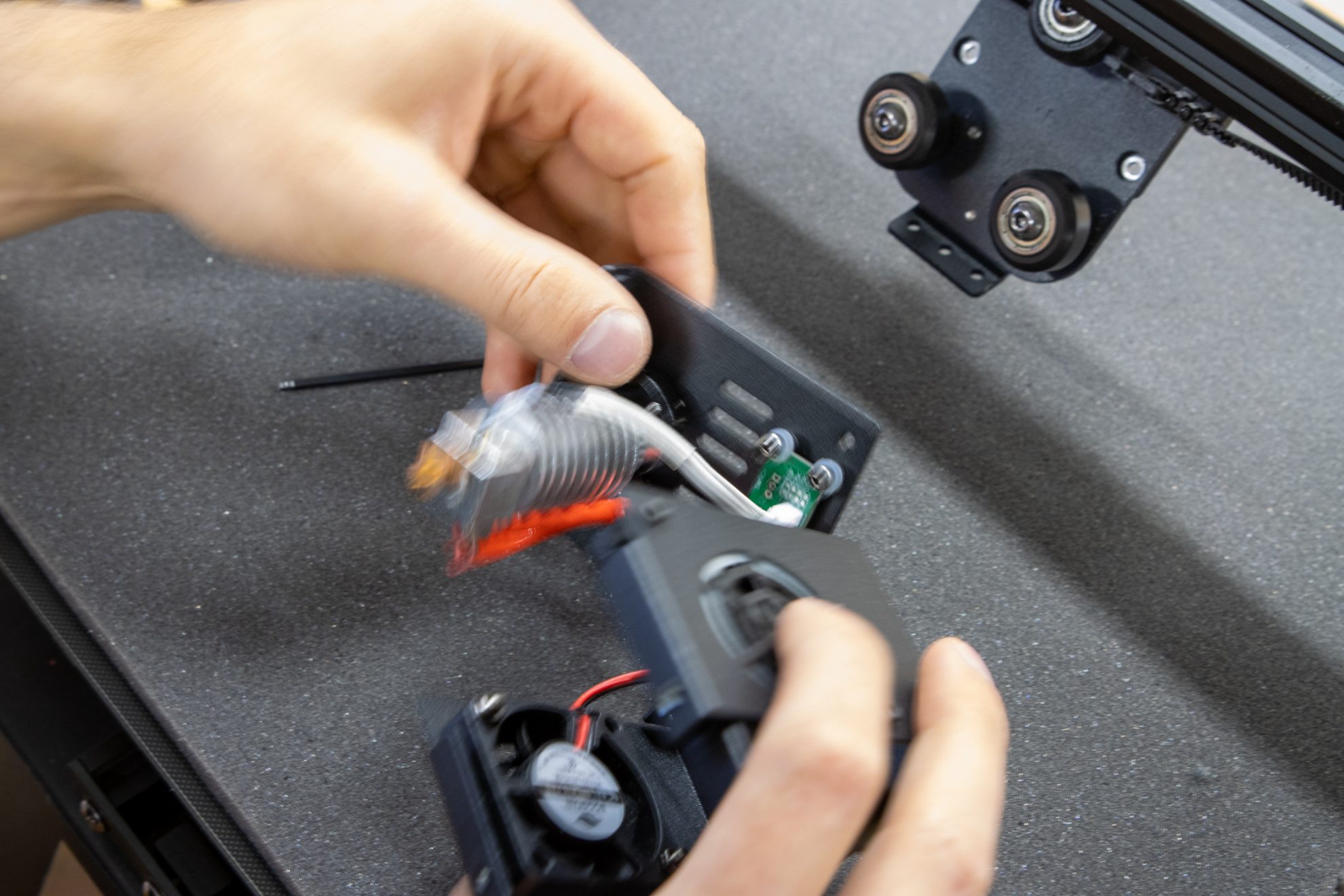
Detach top plate with hotend and breakout board.

Release this screw.

Release this screw.

Release the part cooling fan.

Use a pliers and hex key to remove this screw.

Use a pliers and hex key to remove this screw.

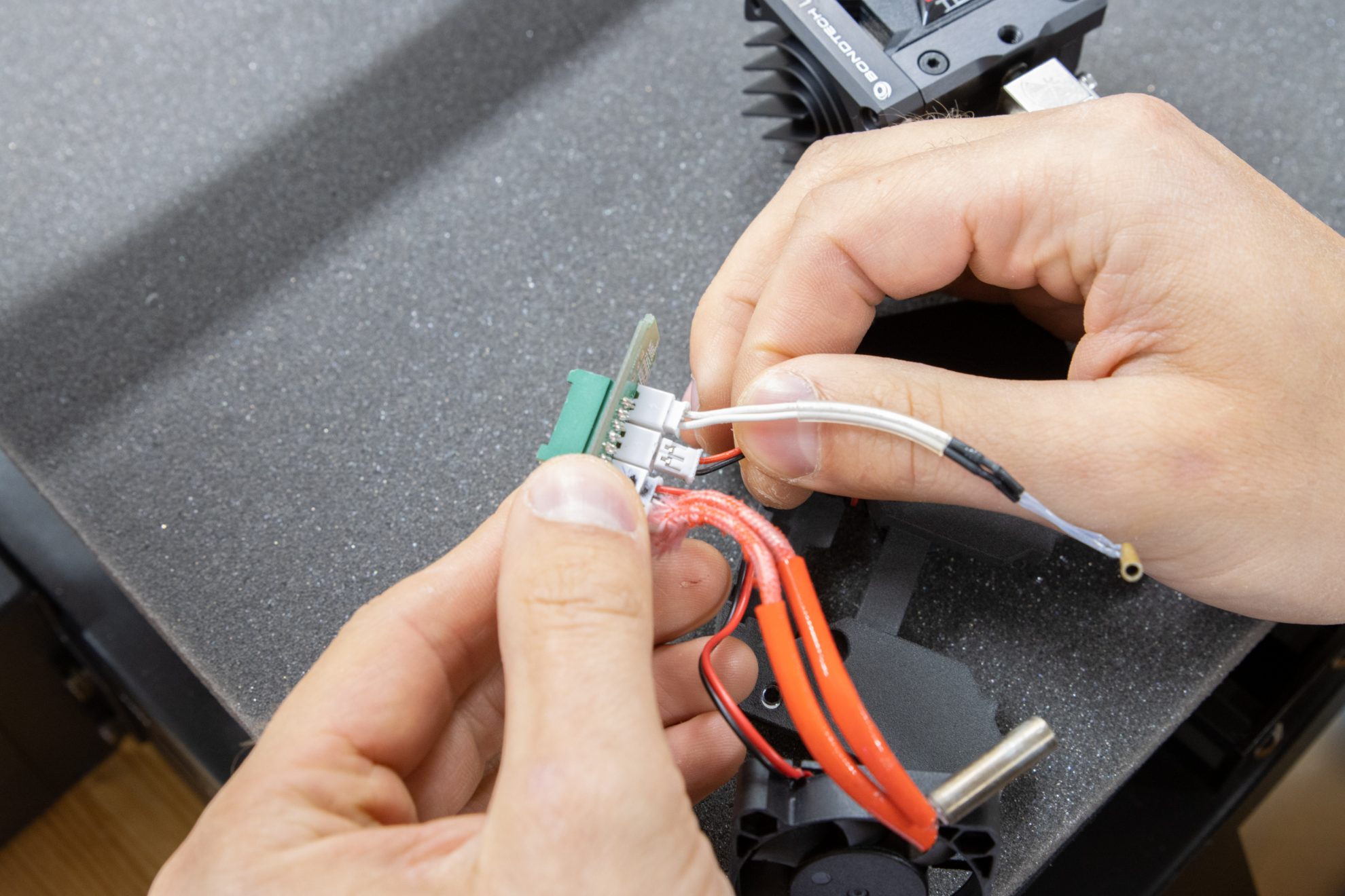
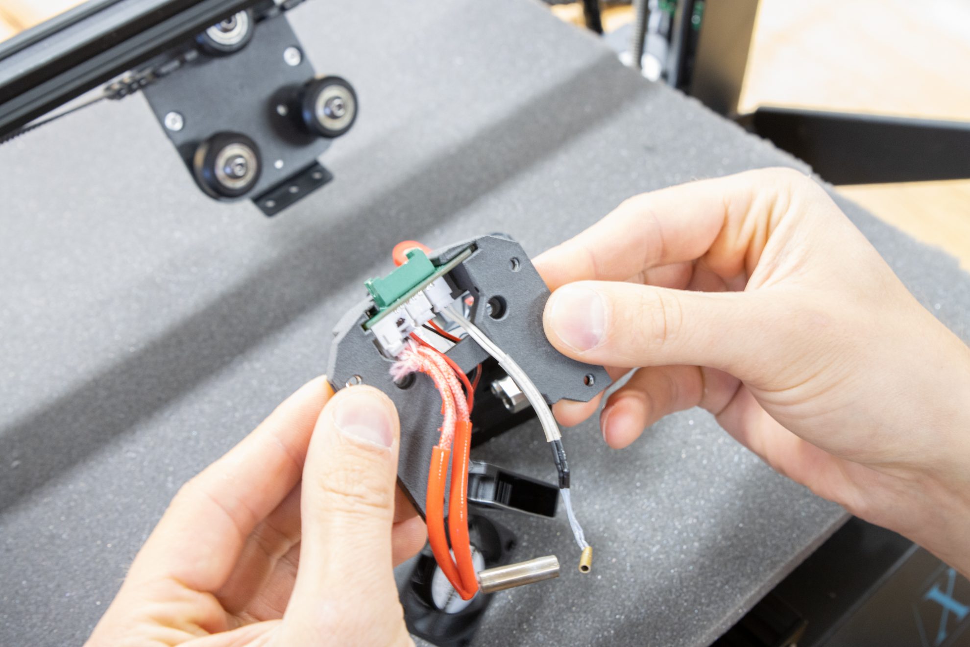
Breakout board, fans, heater and thermistor will be re-used.
Step 7. Extract re-usable items

Remove this set screw.
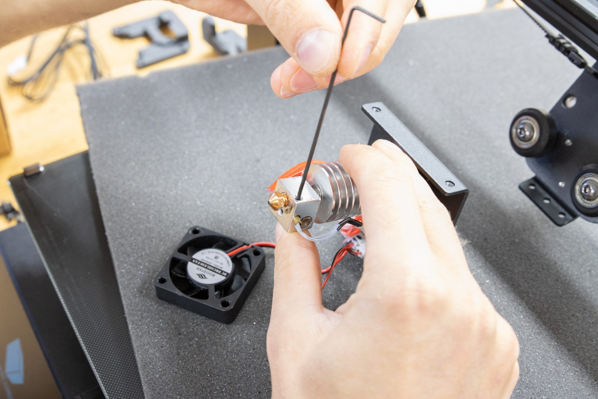
Remove this set screw.

Remove the thermistor from the hot block.

Remove the heater from the hot block.

Remove this screw attaching the breakout board...

... and all the other screws attaching the breakout board.

Remove the whole set from the print head plate.

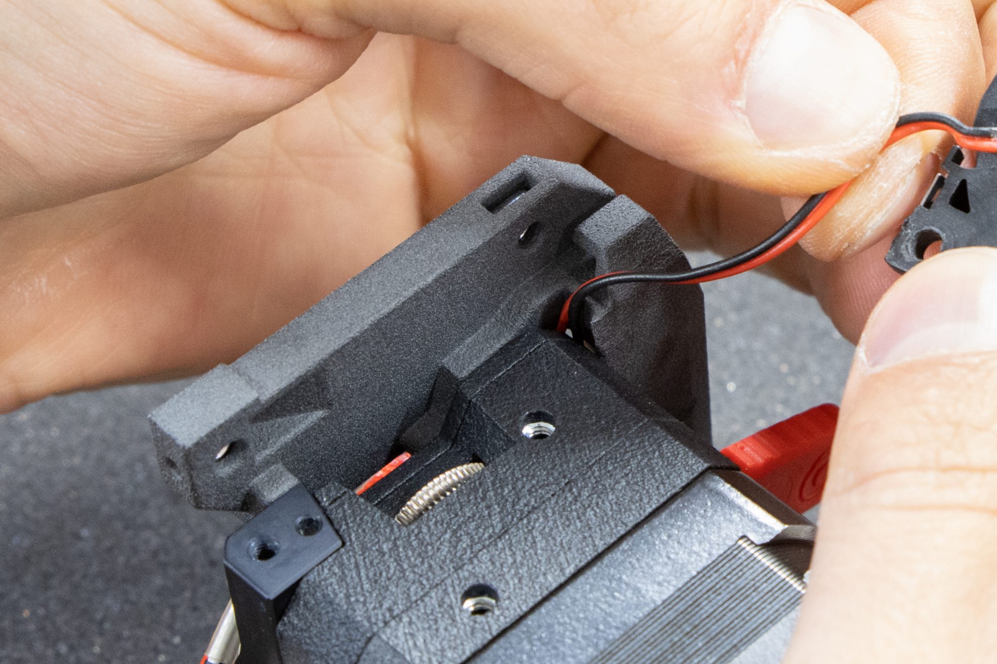
Unplug the fan connectors.

Reserve the re-usable items.
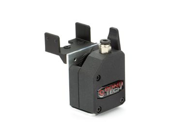
Step 1. Prepare LGX with Shortcut hotend
Setting up the LGX Shortcut Copperhead on the LGX extruder.
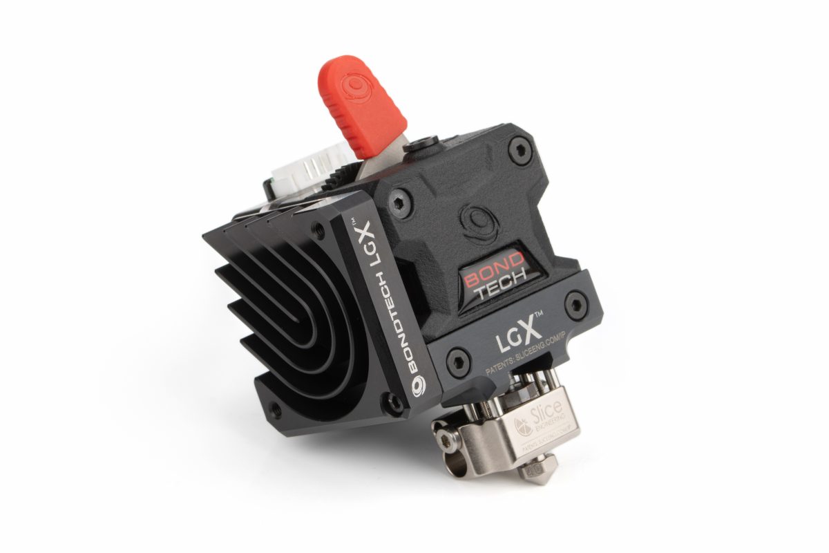
Use the same guide to set up the LGX Shortcut Mosquito.
The video guide above shows how to setup the LGX Shortcut Copperhead printhead. To use on this upgrade kit though, the Copperhead hot block's logo should face forward as seen in the pictures below.
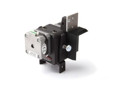
Step 2. Check the parts before installation

On the x-carriage mount...

... check if it has 4 square nuts installed.

Here are all the elements you need to setup the LGX Shortcut on Mega-X
Step 3. Assemble the print head

Pass part cooling fan cable through the mount plate.
Plug the part cooling fan cables into the breakout board.

Apply the breakout board and connector to the mount plate.
Only the part cooling fan cable crosses through the mount plate's to the front side.
See here how to guide the part cooling fan cable through the mount.

Remove the 2 top screws of the LGX Shortcut.
Align the holes on the mount plate with the holes on the LGX shortcut.

Use the M3x16 and M3x35 screws to hold them together using the 2.5mm hex key.

Check cable management before tightening the mount plate to the LGX Shortcut.

Tighten the 2 screws with the 2.5mm hex key.

Guide the hotend cooling fan cable.

Install the hotend cooling fan on the Shortcut heat sink using 2 M3x10 screws.

Remove the heat block retaining screw on the left side facing the LGX.
Before installing the heater and thermistor inside the hot block slots, it is recommended to apply thermal grease to their outter surface, preferably Boron Nitride Paste from Slice Engineering, for better thermal performance.

Install the thermistor on its respective slot.

Install the heater on its respective slot.

Tighten the heat block’s retaining screw enough so the thermistor and heater are secured.

Guide the part cooling fan cable away from the LGX side mounting holes.

Install the fan shroud onto the LGX side mounting holes pattern.

Tighten the heat block’s retaining screw enough so the thermistor and heater are secured.
Mind there are two holes patterns on the fan shroud. Upper holes (marked with M) to use with Shortcut Mosquito. Bottom holes (marked with C) to use with Shortcut Copperhead

Align the part cooling fan with the fan shroud.

Fit and slide it onto the fan shroud insert on the left hand side first.

Then swing it and snap it into place.
If you have a Mega-S or Mega-P(ro)
Because the Mega-S and Mega-P use a different method to hold the x-axis belt a slightly different process must be used to install this upgrade.
If you have a Anycubic Mega-X, skip this section.
Step 1. Align the mount plate with the x-carriage plate
Align the spacer with the 2 x-carriage bottom screw holes.

Use the
2 M3x10 screws...
... to hold
the spacer in place.
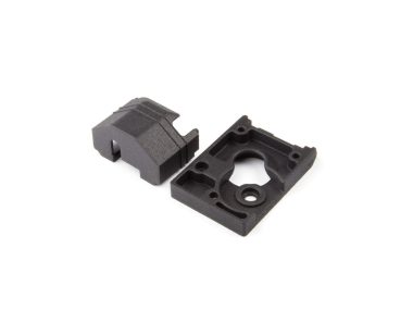
Step 2. Prepare the x-axis belt holder

Use the belt holder with 2 M3x 16 (re-used from the stock hotend cooling fan).

Align it
with these 2 x-carriage plate holes.

Align the belt holder holes
with the spacer's and mount plate's...

... and use the 2 M3x16 screws
to hold it in position.

Tighten this
bottom left M3x10 screw...

... and tighten this
bottom right M3x10 screw.
Step 3. Install the x-axis belt
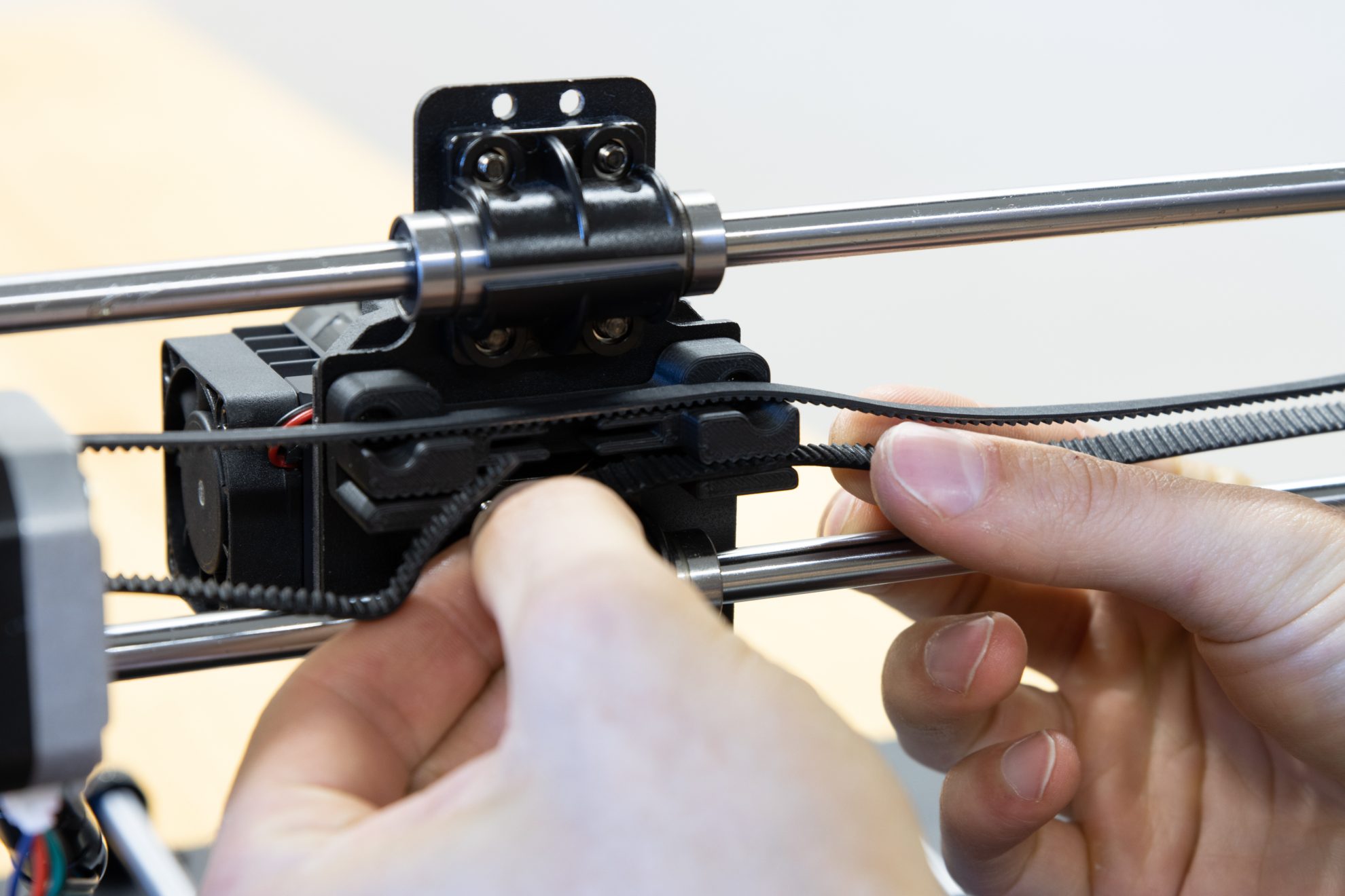
Grab both tips of the belt.

Stretch and pull them to the grooves.

Make sure the teeth are aligned.

Fold the tips into the slots.
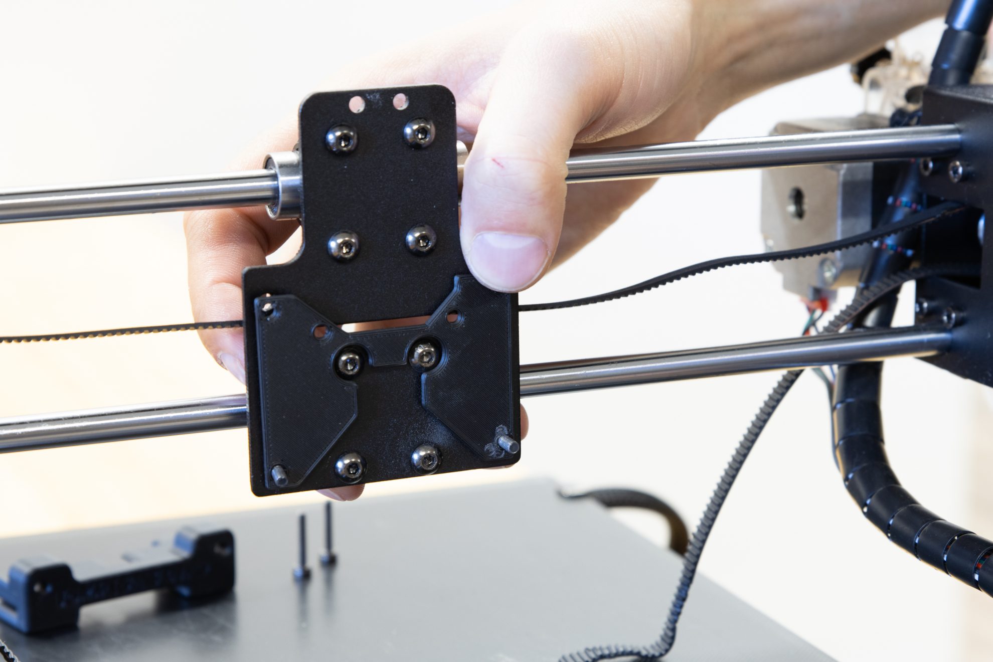
Step 1. Identifying what screws go where
For the next step we will need 4 screws that hold the print head to the x-carriage plate.
- 2x M3x8 screws that will fasten the print head using the 2 holes (top and bottom) on the heat sink side.
- 2x M3x10 screws that will fasten the print head using the 2 holes (top and bottom) on the fan shroud side.
use the 2.5mm hex key and align the extruder straight with the mount before tightening.
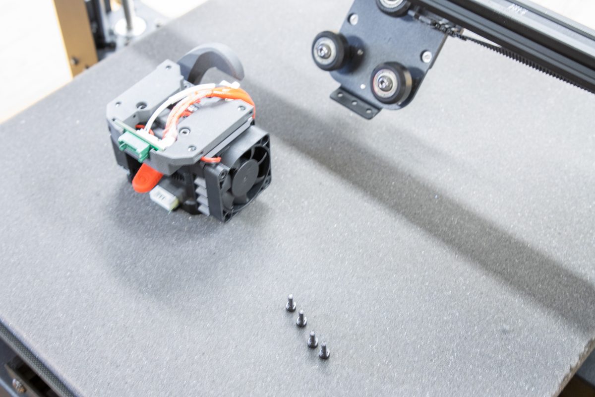
Step 2. Mount the print head onto the x-carriage plate

Hold the print head and tilt the x-carriage plate.
Align the mount plate with the 4 holes of the x-carriage plate.

Use the M3x8 and M3x10 screws to attach the print head. Verify alignment before tightening.
Step 3. Mount the x-carriage back on the x-axis profile

Lift the x-carriage and fit the bottom wheel on the bottom groove while holding back the two top wheels.

Holding the bottom wheel against the bottom groove rotate the carriage to move the top wheels onto the top groove.

Using again the 8mm wrench and the 3mm hex key, hold the nuts and tighten the screws of the top and bottom wheels.
Step 4. Verify and fine tune the x-carriage movement

Hold the x-carriage
by the top flange...

... and move it left to right to check it rolls smoothly.
Tweak it if necessary using the eccentric nut from the bottom wheel.
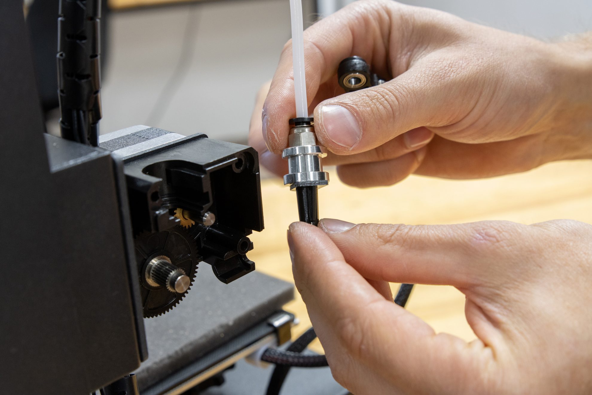
Step 1. Plug in PTFE tube and main cable

Insert the PTFE tube into the LGX push-fit collet.

Plug the main cable to the breakout board.
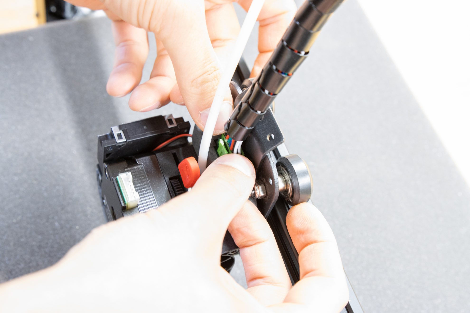
Press it all the way down.
Step 2. Check and plug the stepper motor cable extension
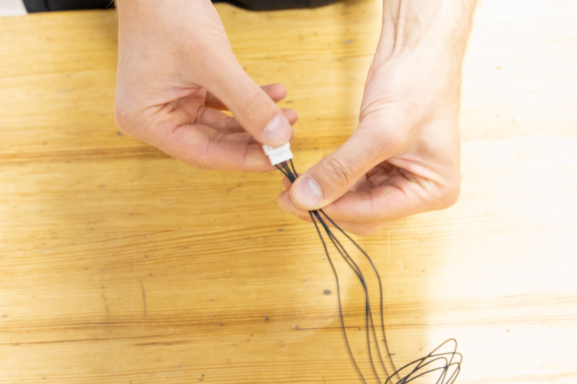
Hold the connector and slide your fingers along the wires.

Slide throughout the whole length of the cable.

Make sure none of the wires is crossed.

Plug the cable and route it.

Use a hex key to fit the cable inside the guide.
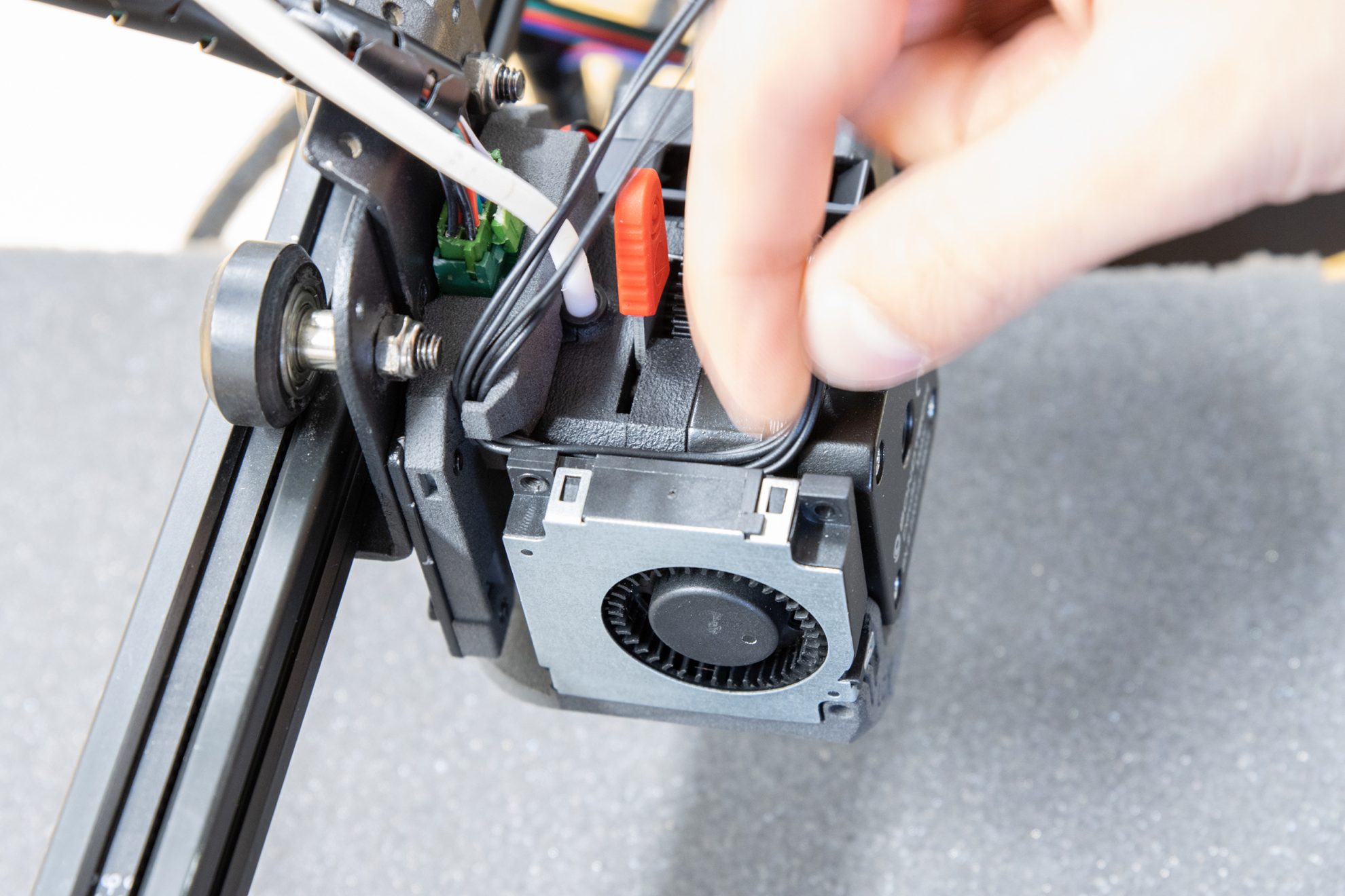
Re-channel the cable if necessary.

Insert the stepper motor cable inside the main cable sleeve...

... and guide it...

... until the end of the sleeve.

Take the stock stepper motor cable connector...

... and unplug it.

Connect it to the Bondtech stepper motor extension cable.
Step 3. Convert the stock extruder into a pass through

Unscrew the extruder cover...

... and remove it.

Pull the hinge out.
Pull the bowden adapter out.

Remove the main drive gear.

Put the bowden adapter back in.

Put the hinge back in.

Put the cover back on.
Step 4. Tiddy-up!

Tuck the stepper motor cable...

... between the stock extruder and the frame.

Use zip ties to hold the main cable and PTFE tube to the x-carriage plate.

Use the supplied cable clips...

... to tidy-up the main cable and PTFE tube.

And snip the zip-ties ends.
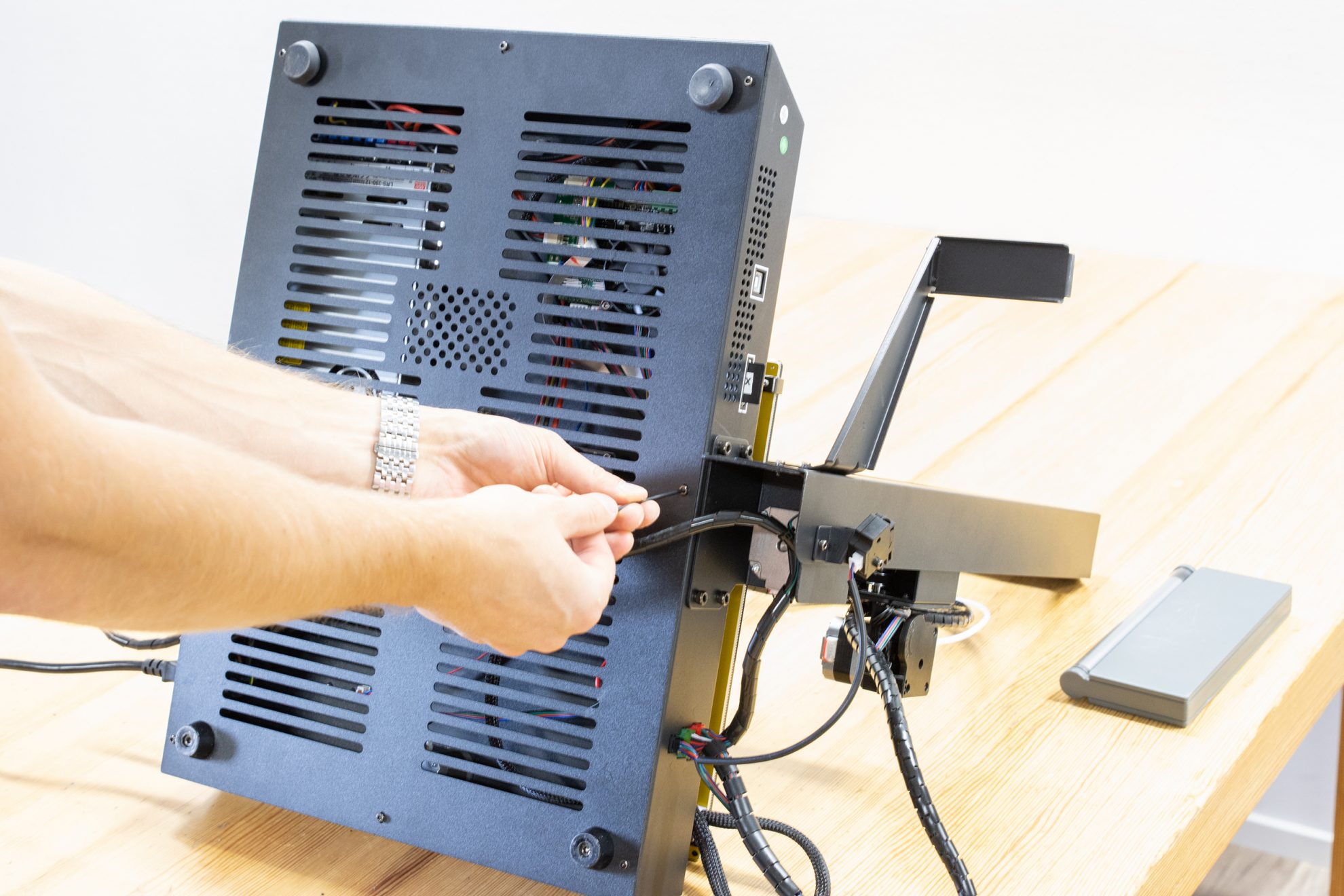
Step 1. Accessing the extruder's stepper motor driver

Remove the bottom cover.

Turn the printer ON.
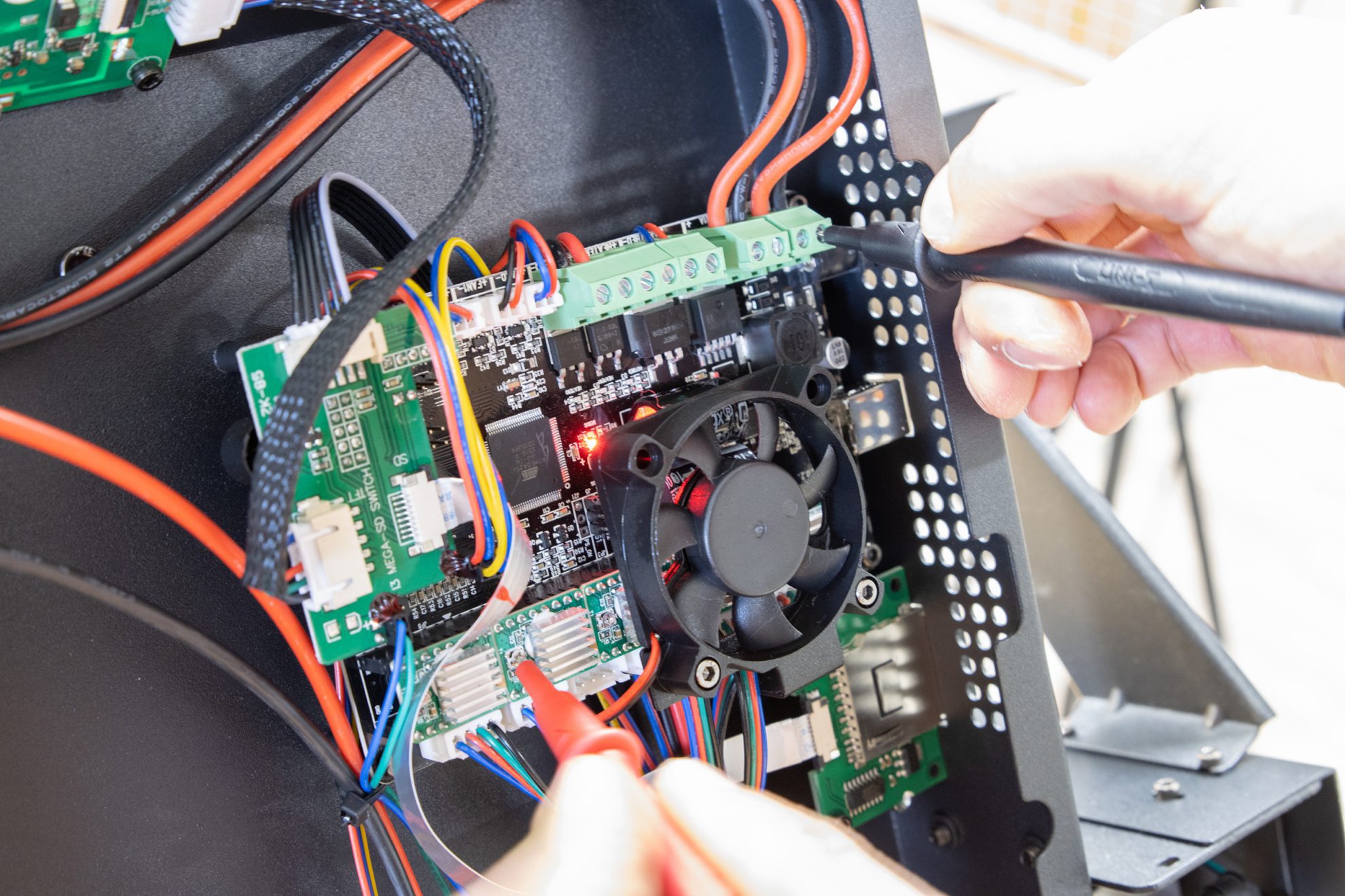
Use a multi-meter to measure the Vref.
It is very important that the multimeter is set to Voltage DC while measuring. Find the Extruder driver on the mainboard. Be sure to touch only the stepper motor driver potentiometer with the red probe tip and the negative voltage supply to the board with the black probe tip.
Step 2. Adjusting the Vref from 0.9 to 0.5V

Stock reading will be about 0.9V

Use a screw driver or tool tip...

... and rotate the driver potentiometer counter clockwise to lower Vref.

Measure it. Target value is ~0.5V

Tweak it as many times as necessary...
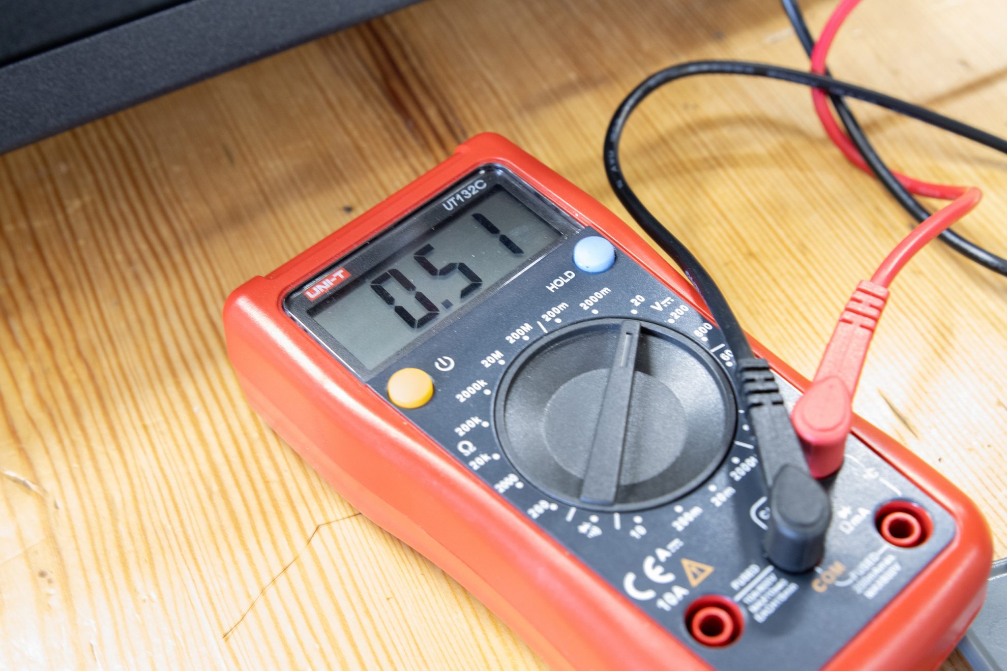
Until you hit as close as you can the 0.5V mark.
Step 3. Wrap it up

Turn the printer OFF.

Put the bottom grid back on.
And fasten it. We're done here.
Step 1. Home the printer

Lower the bed to its max by using the 4 big levelling knobs.

Home the printer using the user interface Tools > ...

... Home > Home Z
Step 2. Bed levelling
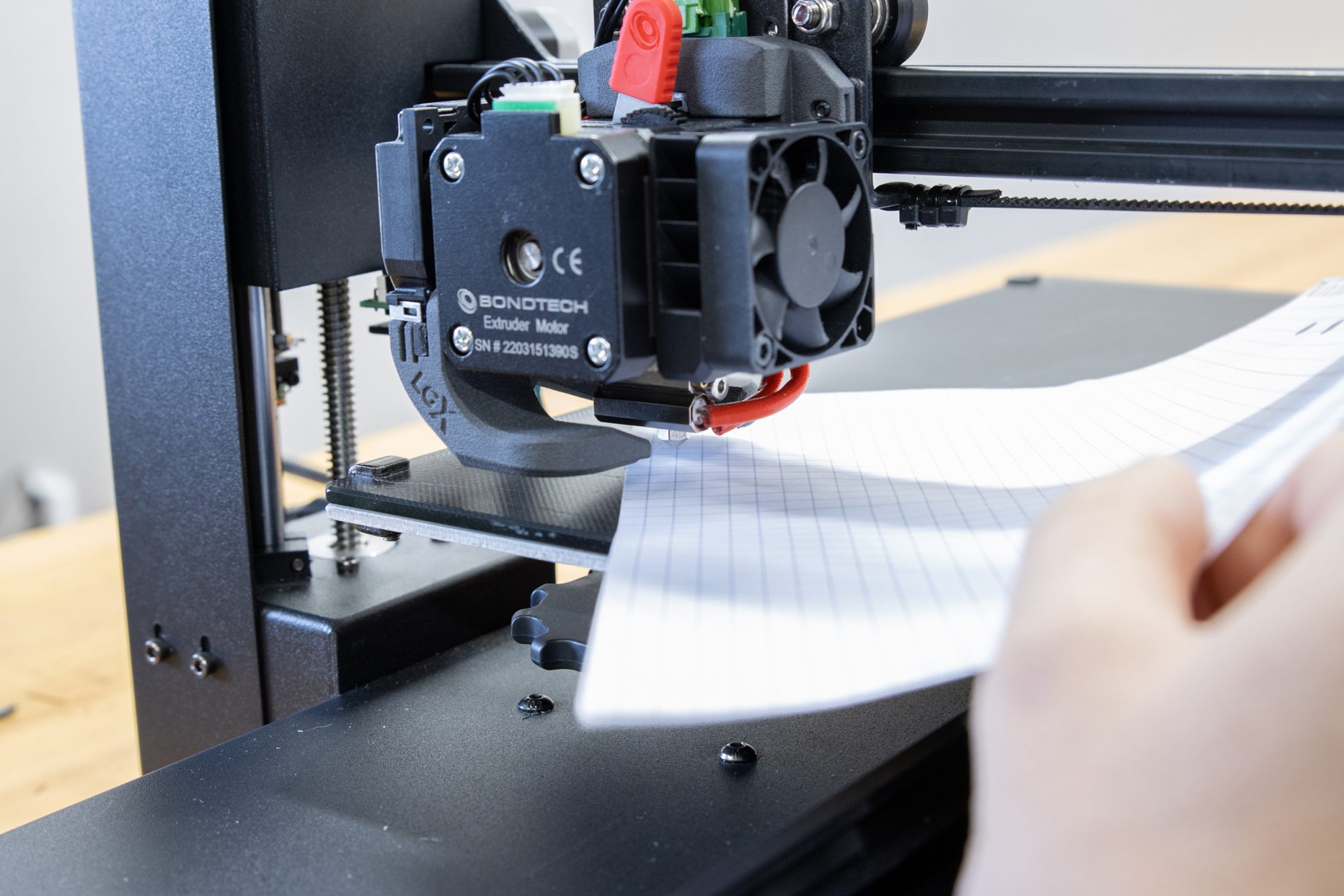
Do the paper gauge levelling sequence...

... over each knob.

If the nozzle still can't reach close enough to the bed perform step 3, Otherwise you are done with bed levelling.
Step 3. Adjust Z-end stop screws
To be on the safe side, perform the process below bit by bit by moving smaller distances at a time (2 full turns of the Z-end stop screws for instance) then repeating the cycle raise the screws / home Z / check the distance over and over until your nozzle is close to 2mm away from the bed.
Lower the bed to its max by using the 4 big levelling knobs.

Use your finger to carefully bend the z-end stop
screw just enough so you can reach with a Philips
screwdriver to unscrew it. Count the full turns.
Begin with the extruder side.

Do the same on the other side, using the same amount of turns.
Home Z-again.

Use a 2.0 mm hex key to check the nozzle is 2mm away from the bed.
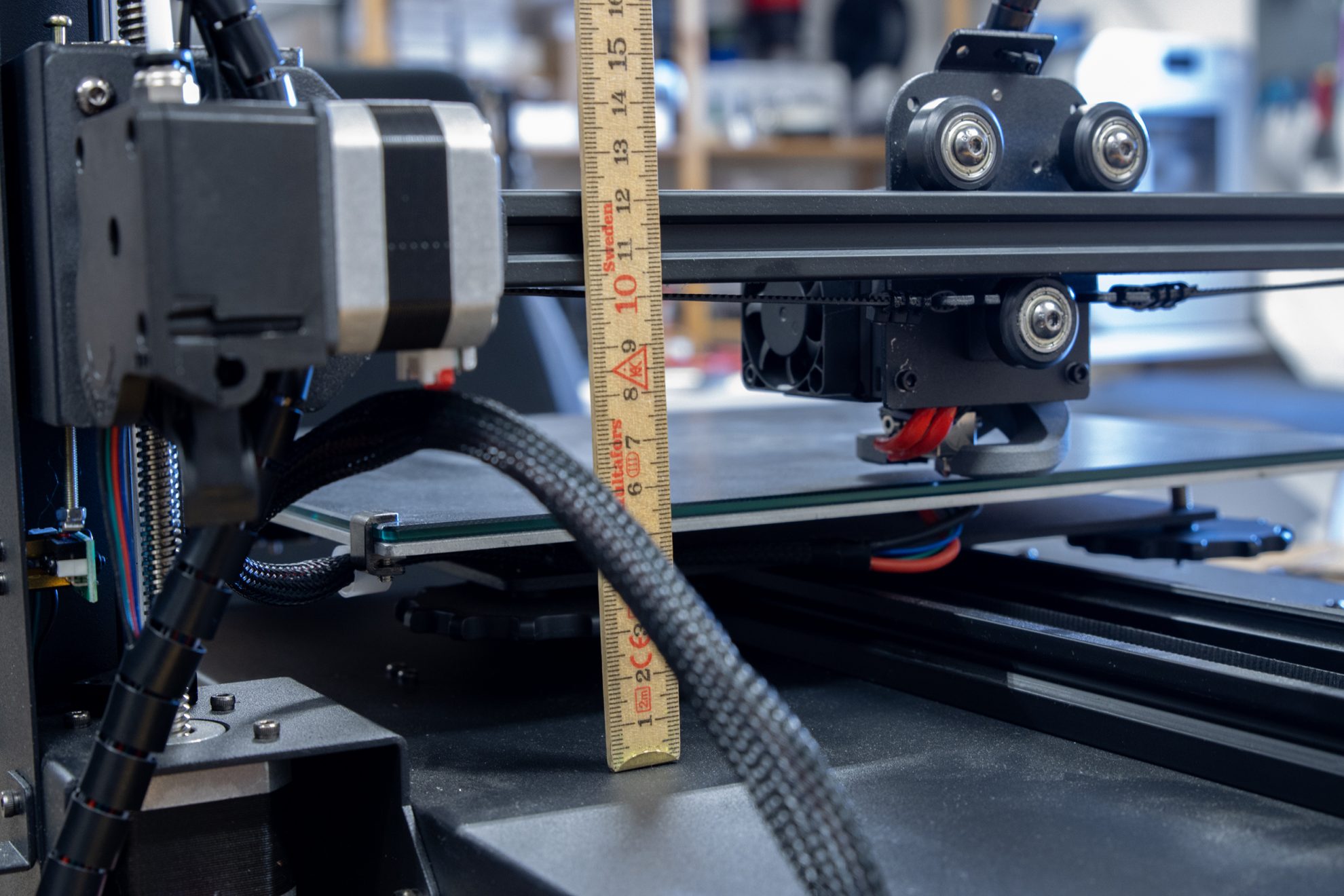
Measure the height from the frame to the x-axis aluminum profile...

... to be sure it is the same at the other side.
Perform Step 2 again.
Adjust the e-steps value
Add the following command to the beginning of the Start G-code:
M92 E400
Locate the Start G-code on the profile you use for your Anycubic on your slicer.
Adjust Retraction Distance
Change the Retraction Distance setting to:
0.6mm
Locate the Retraction Distance under Print Settings on the profile you use for your Anycubic on your slicer.
Compatible Nozzles
If you fix your Raise3D Pro2 with our Set, here are some additional options you should consider.
Printing with non-abrasive materials?
The Coated Brass nozzles with CHT technology from Bondtech enhance the performance of your heat blocks by at least 30%.
Open product page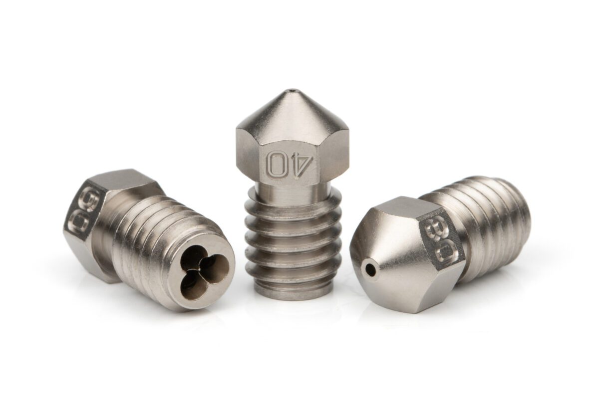
Printing with abrasive materials?
These everlasting Vanadium nozzles from Slice Engineering will give you access to all Carbon or Glass filled materials you will ever need.
Open product page
Printing with materials above 300C?
These abrasive resistant and BridgeMaster copper nozzles from Slice Engineering will give you access to materials you need to process above 300°C, like PEI, PPSU, PEEK, Thermax PSU, hi temp Iglidur and many others..
Open product page
Only logged in customers who have purchased this product may leave a review.
Related products
Reviews
There are no reviews yet.