Introduction

Background

Desktop 3D printers are getting big and bigger. 3D prints follow up. But big usually comes with slow. While there is a rush to find new ways to print faster, there are also many limitations imposed by mechanics, data processing and thermodynamics. Better kinematics, faster mainboards, and higher melt capacity hotends have been at the core of latest improvements.

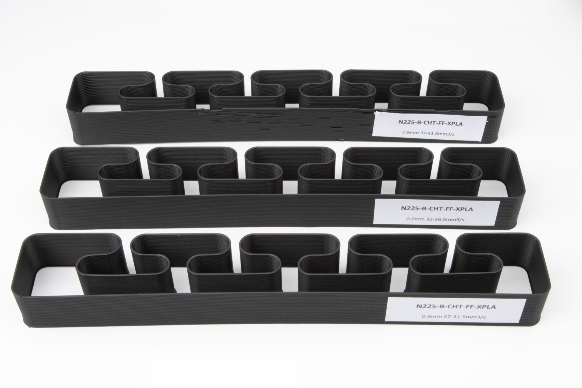
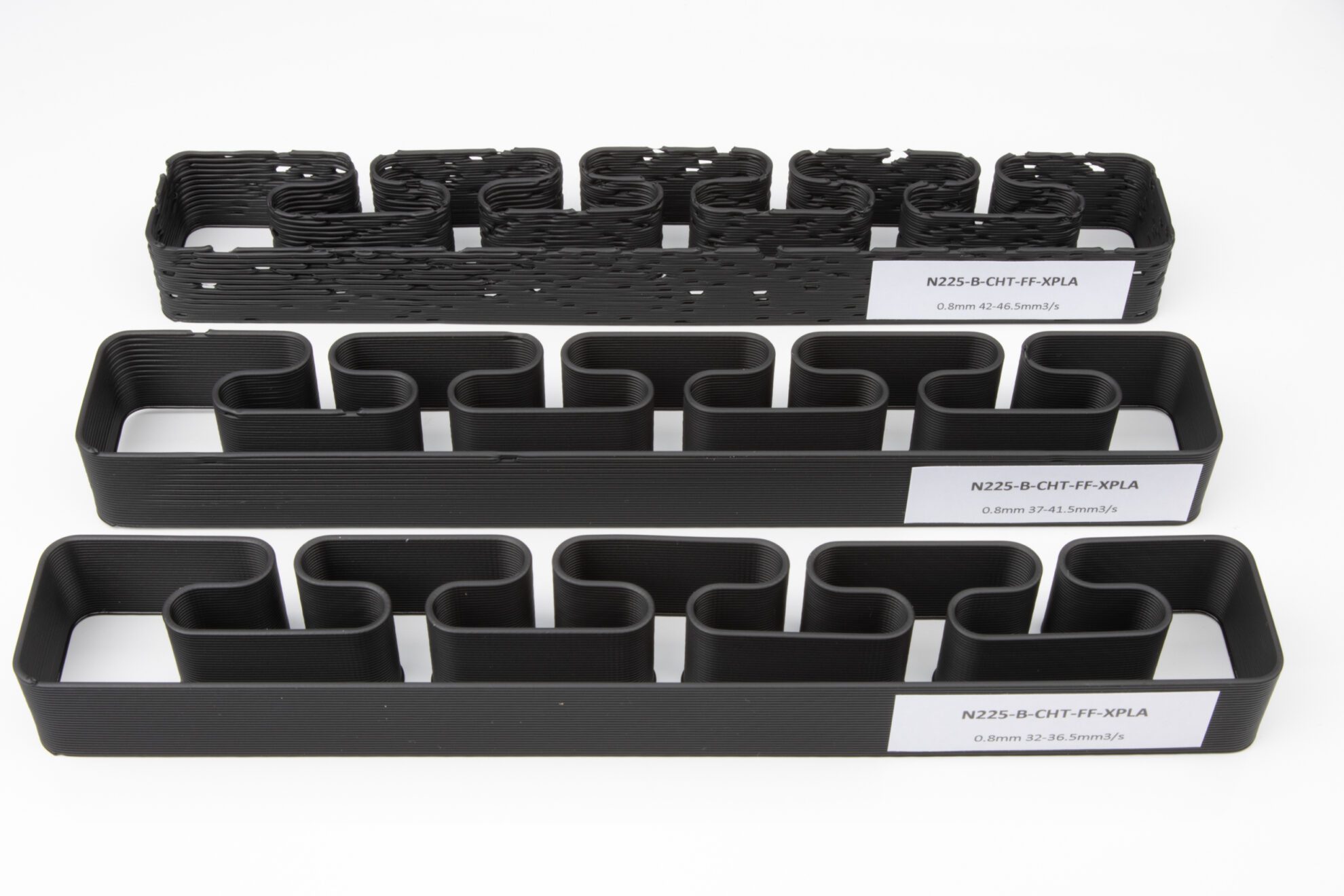
An acknowledgement of Carl Beck and his 2016’s 3DSolex’s Core Heating nozzles impact on melt capacity led to an improvement and optimization of this technology and the development of the Bondtech CHT® Core Heating Technology that is a main subject of this study in what regards to an alternative inlet geometry of the nozzles.

Problem Description

How to raise the limits imposed by thermodynamics on the hotend’s melt capacity?

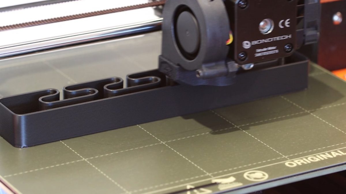
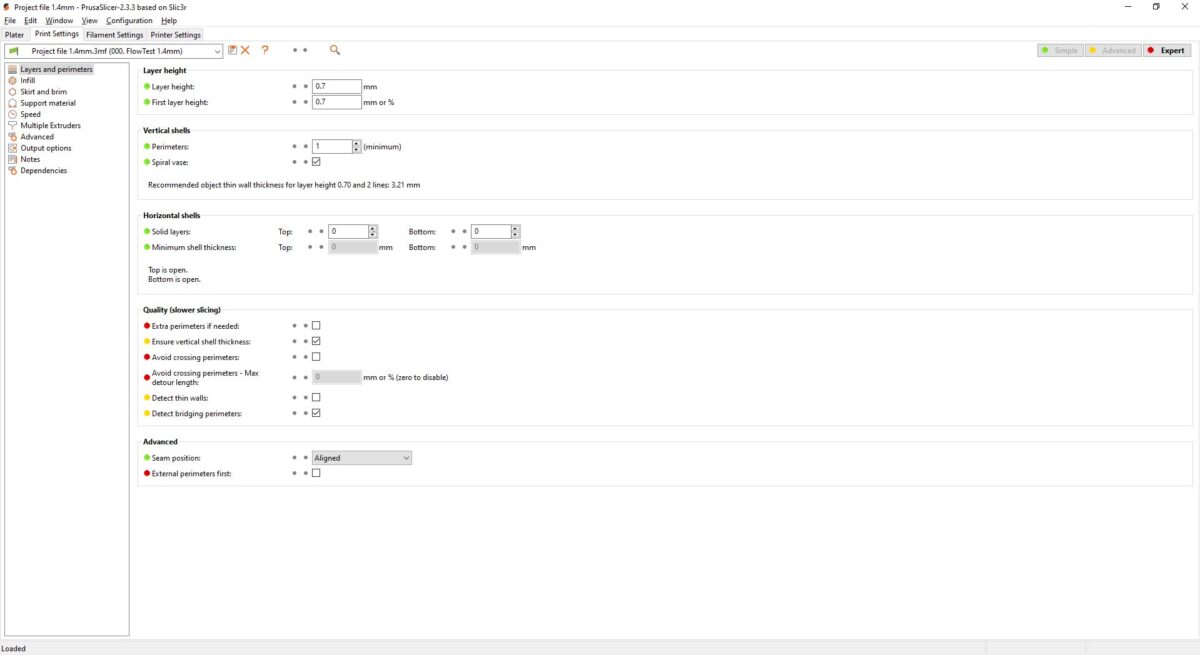
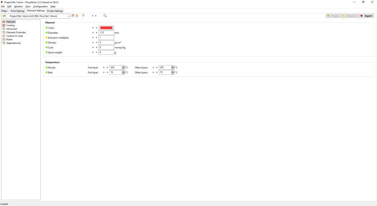
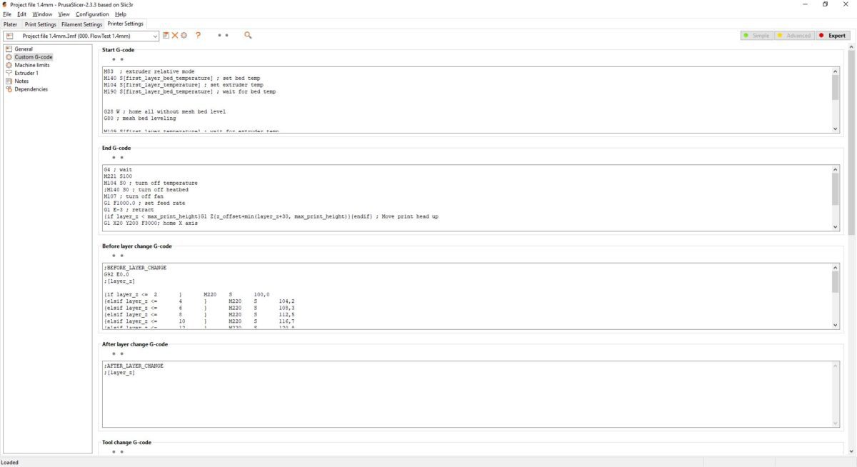
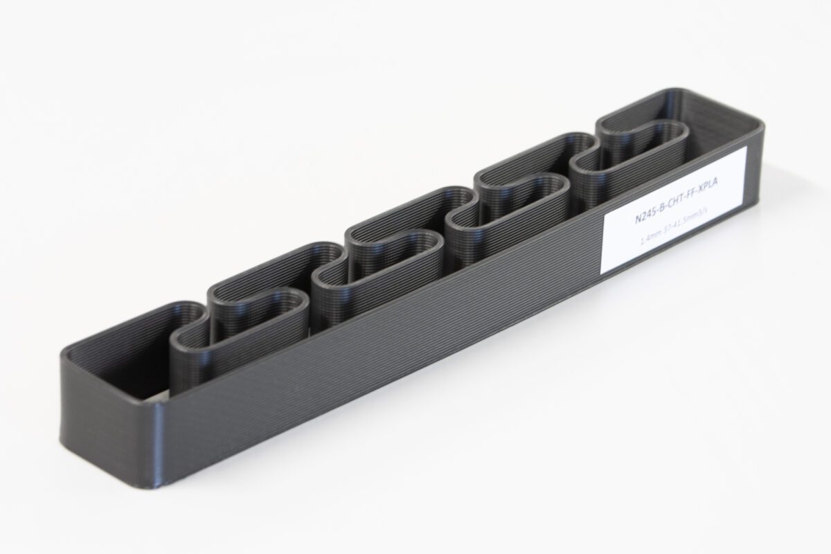
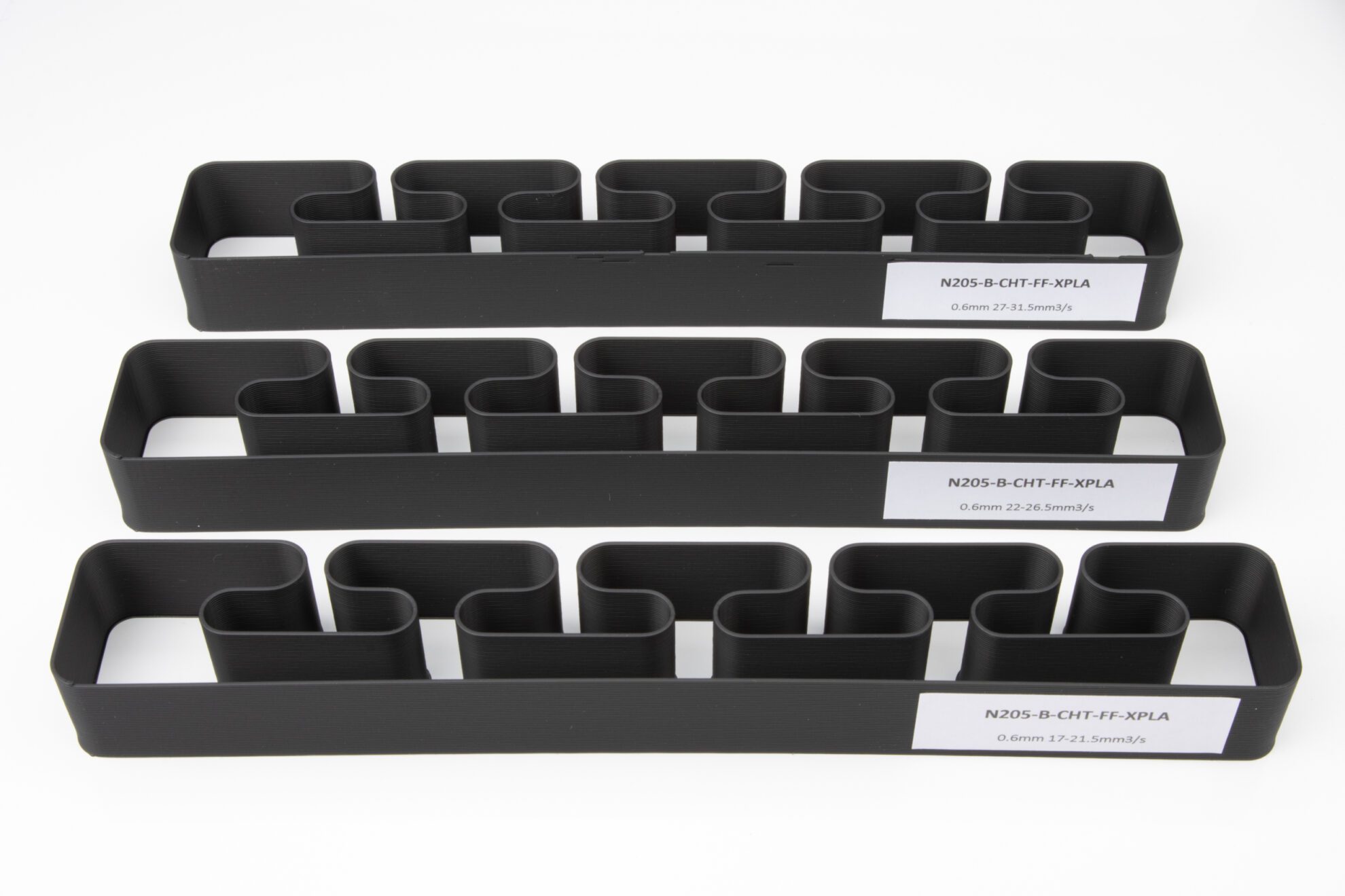
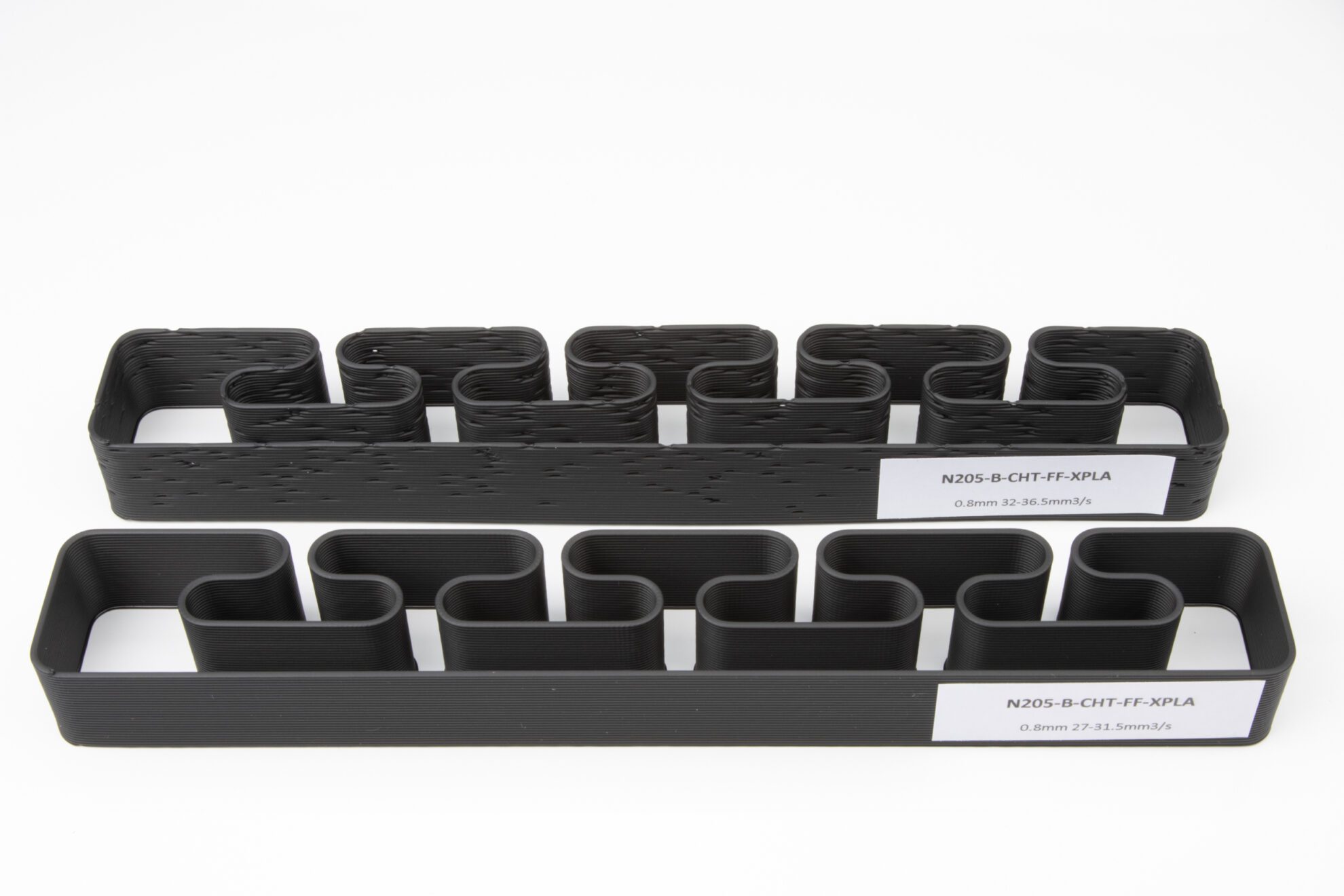
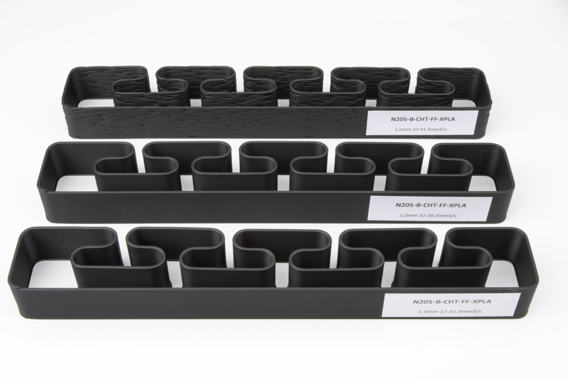
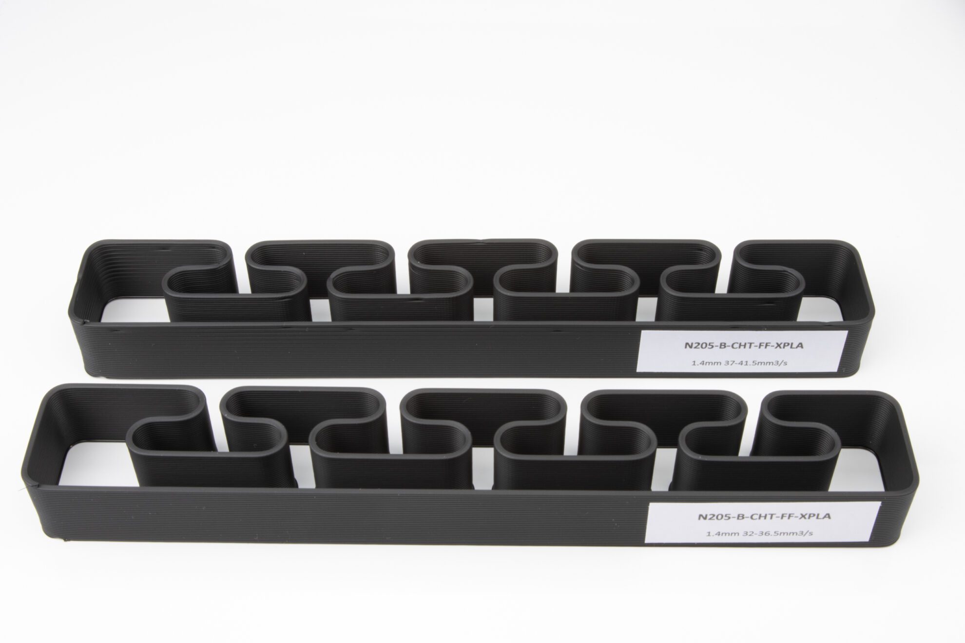
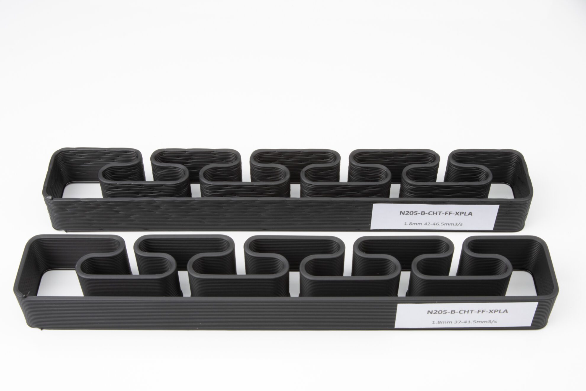
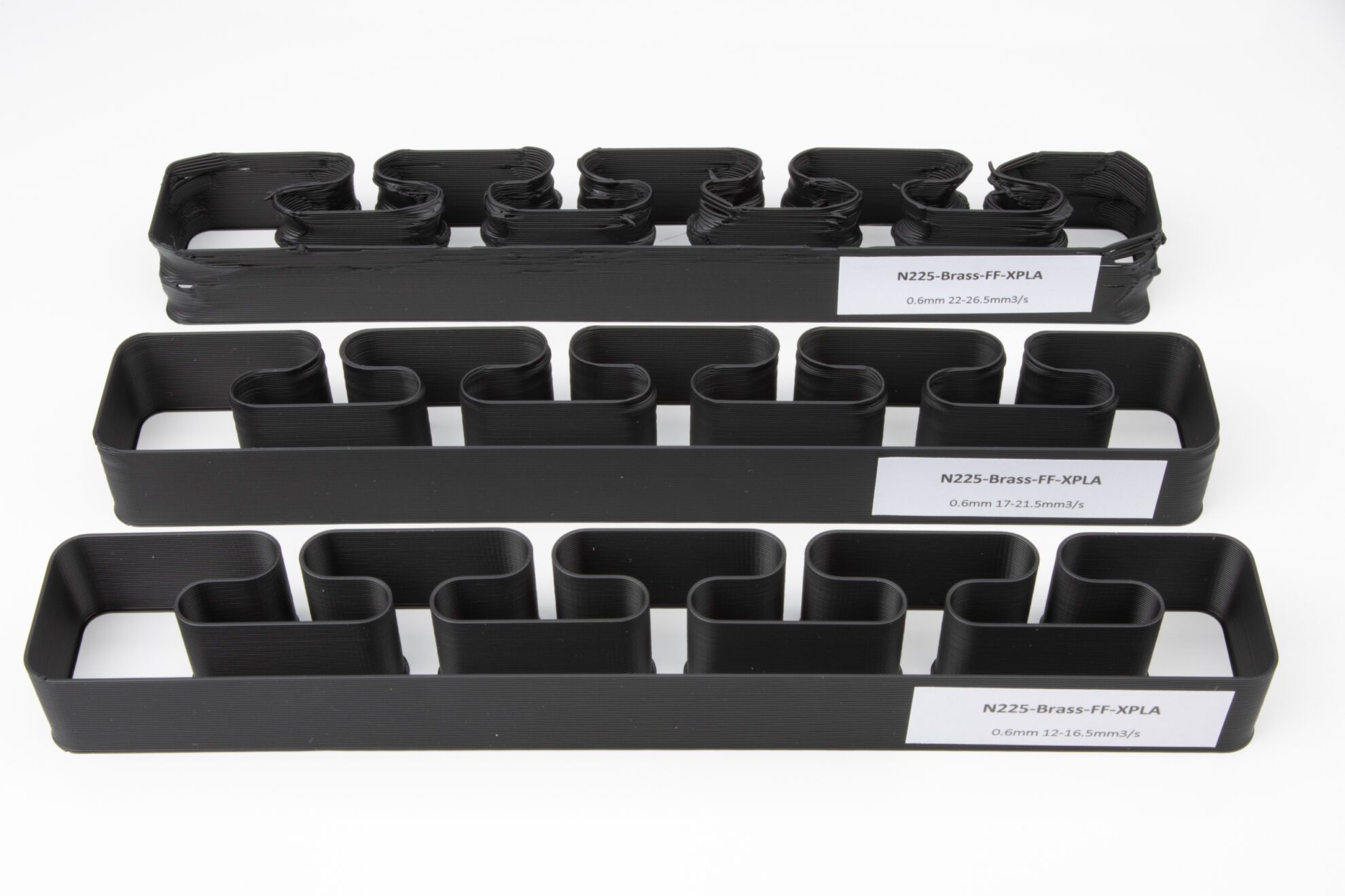
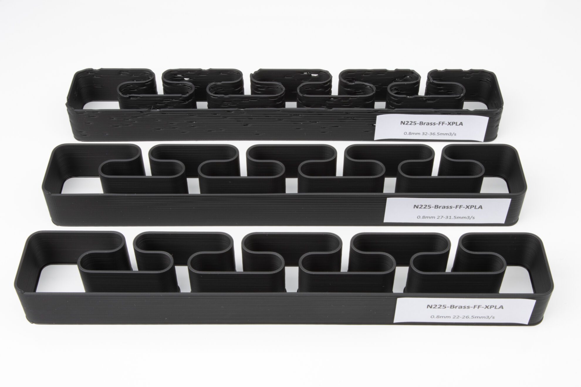
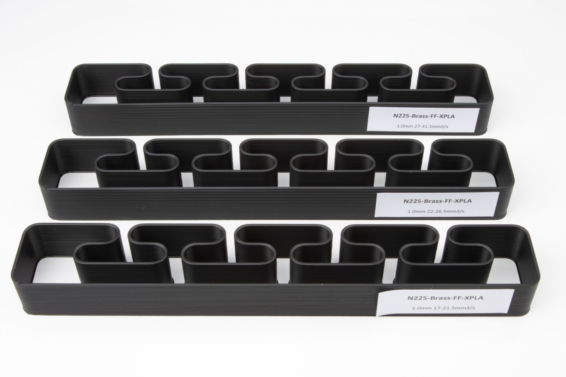
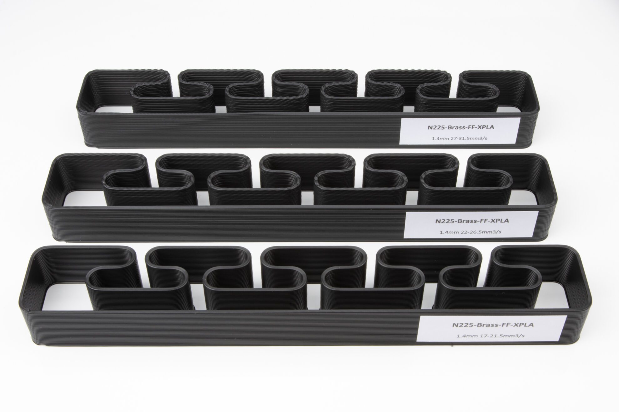
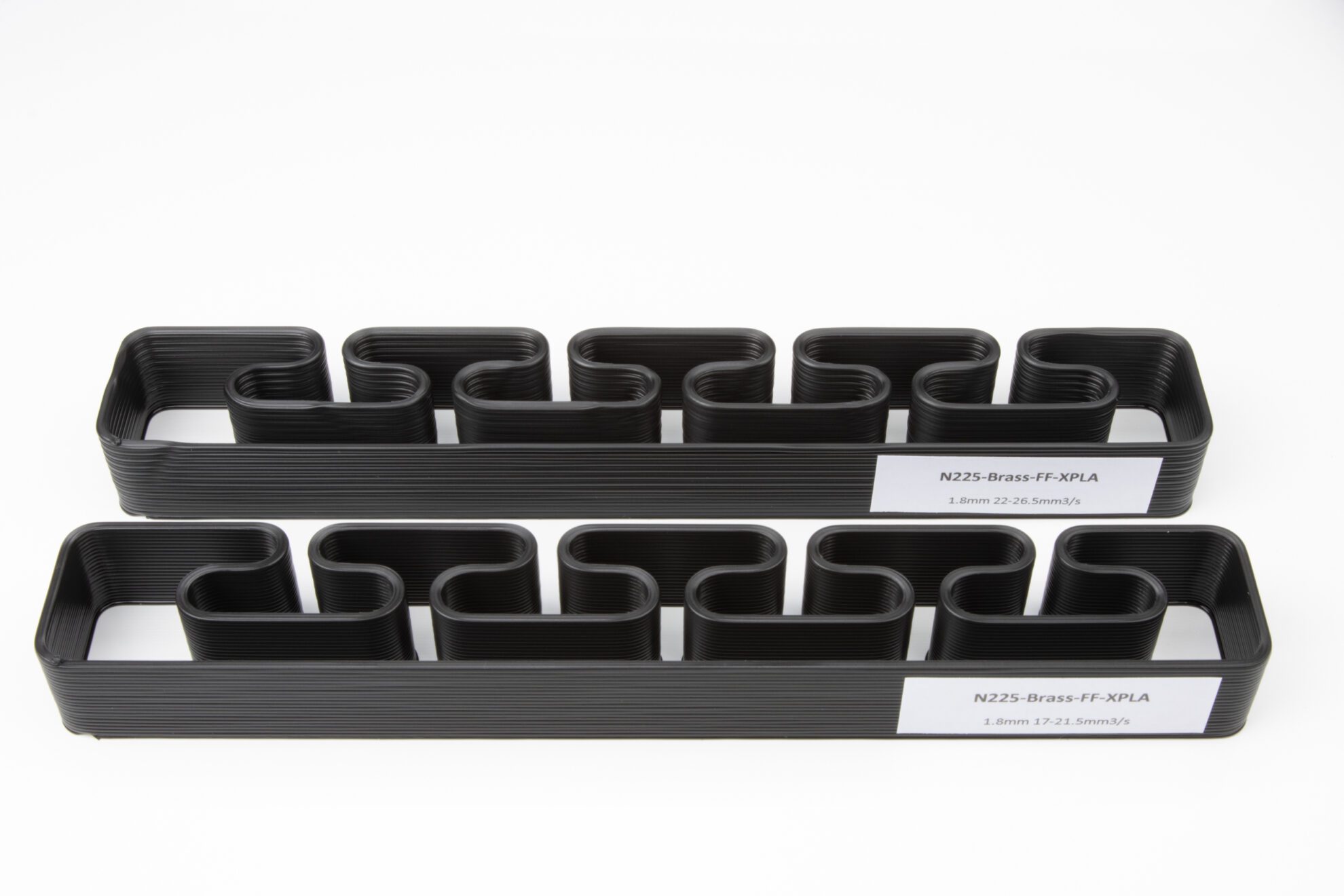
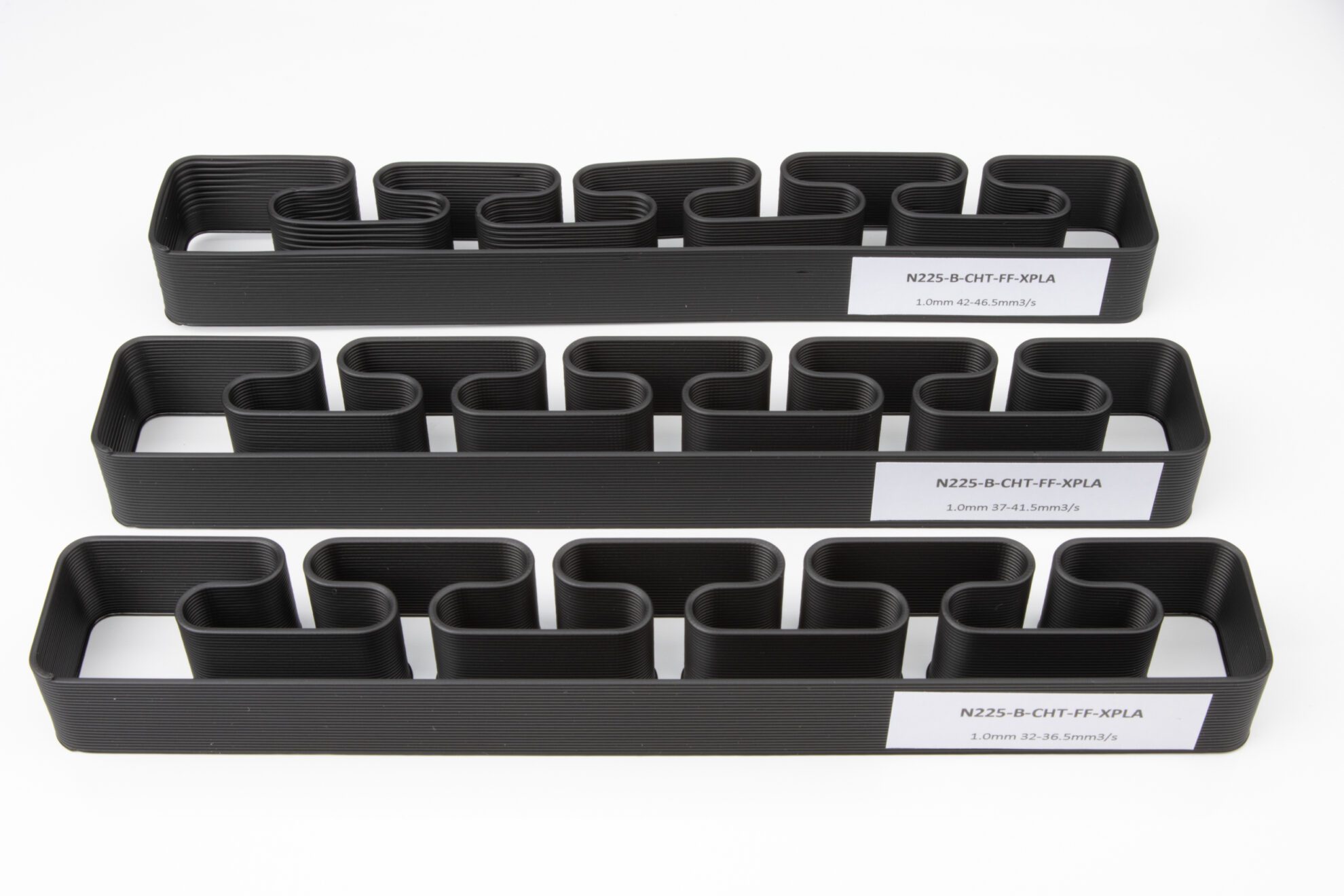
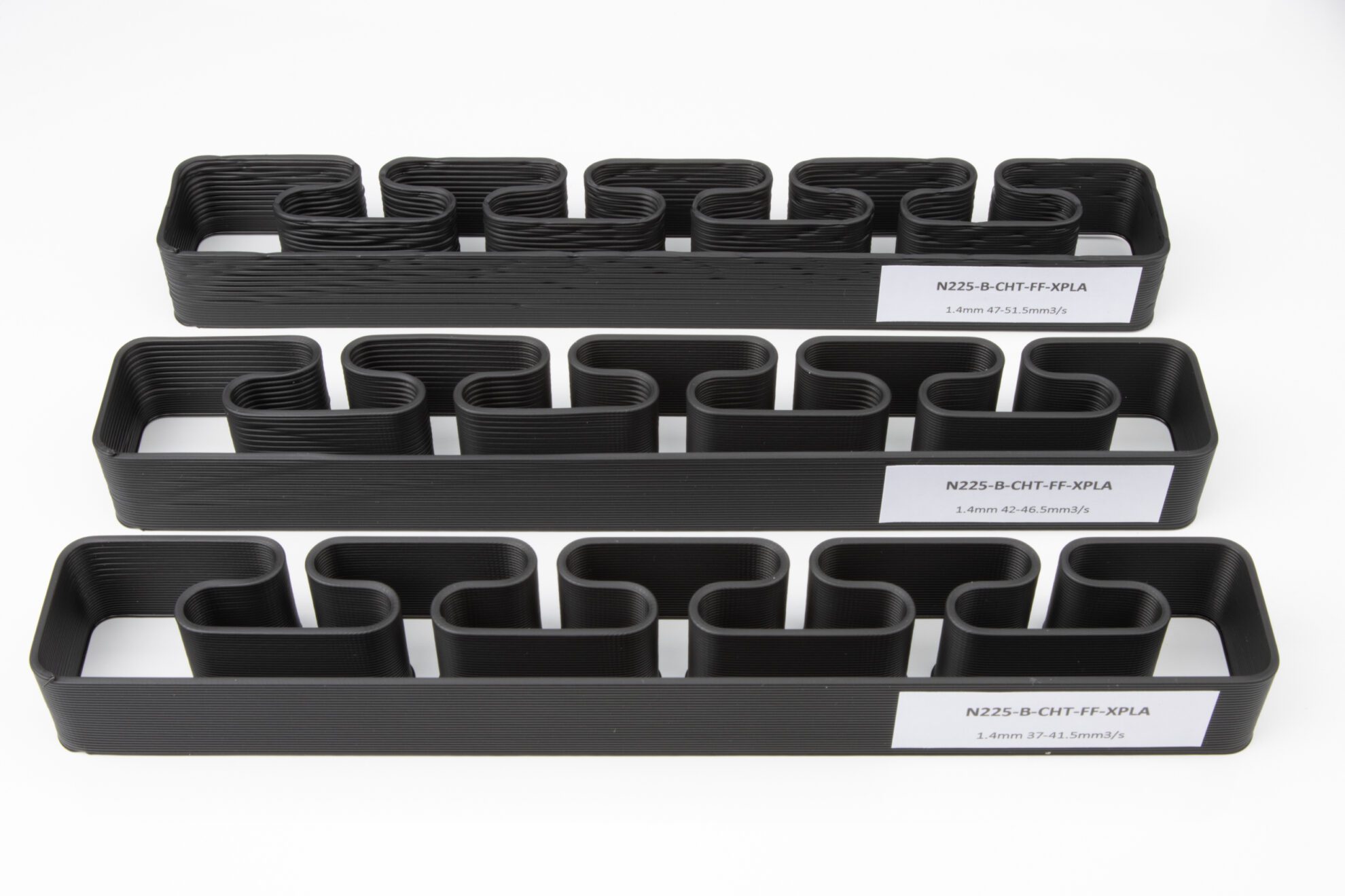
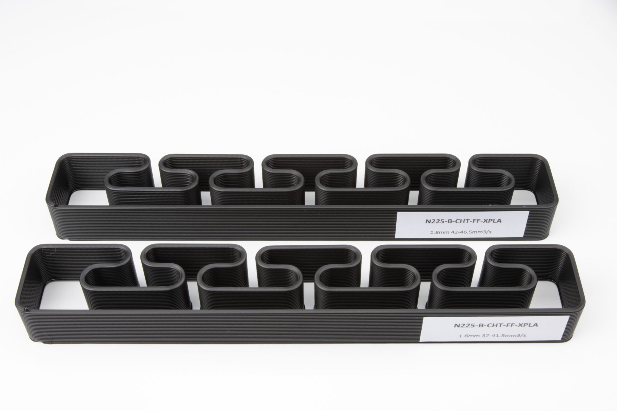
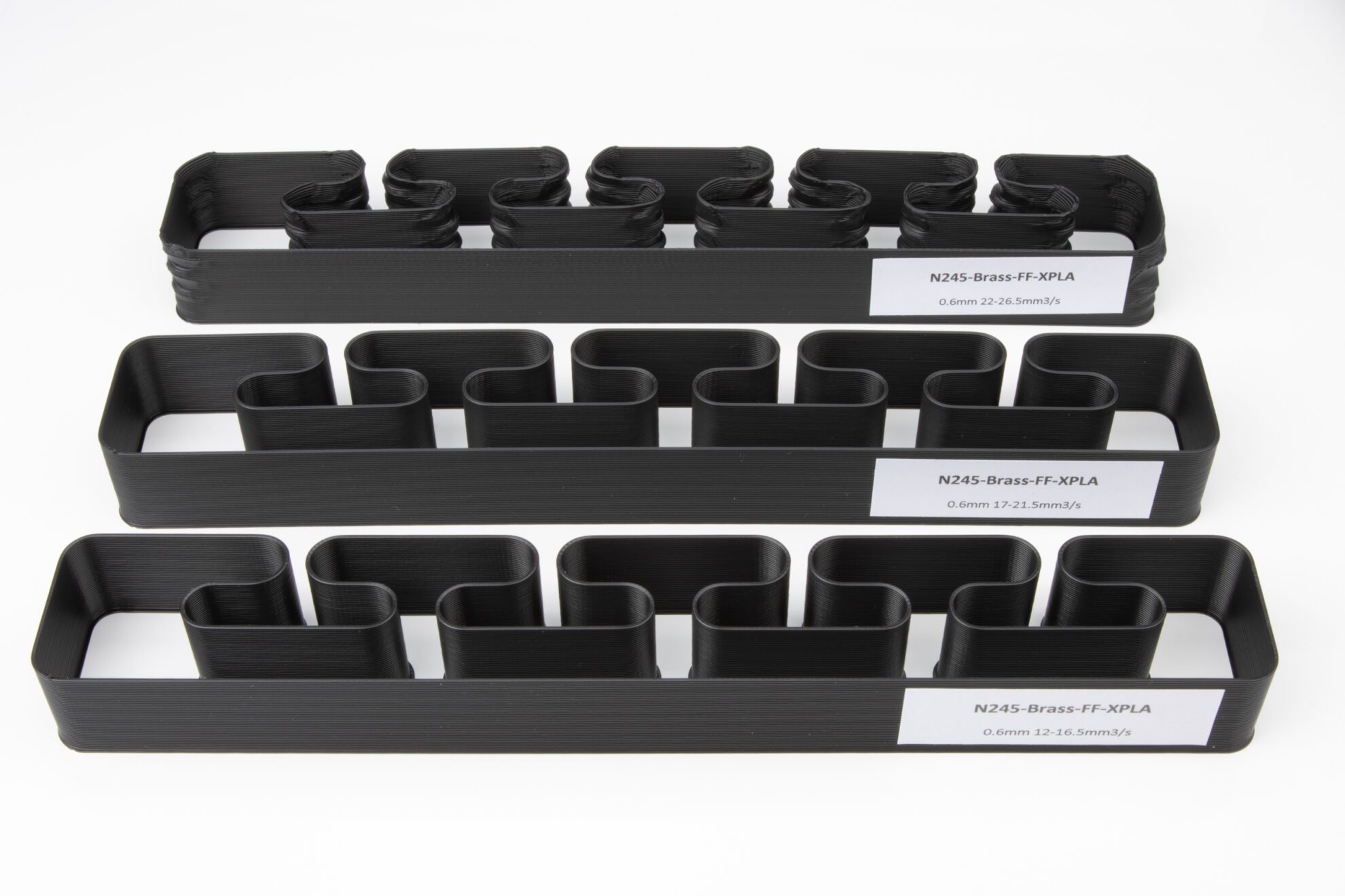
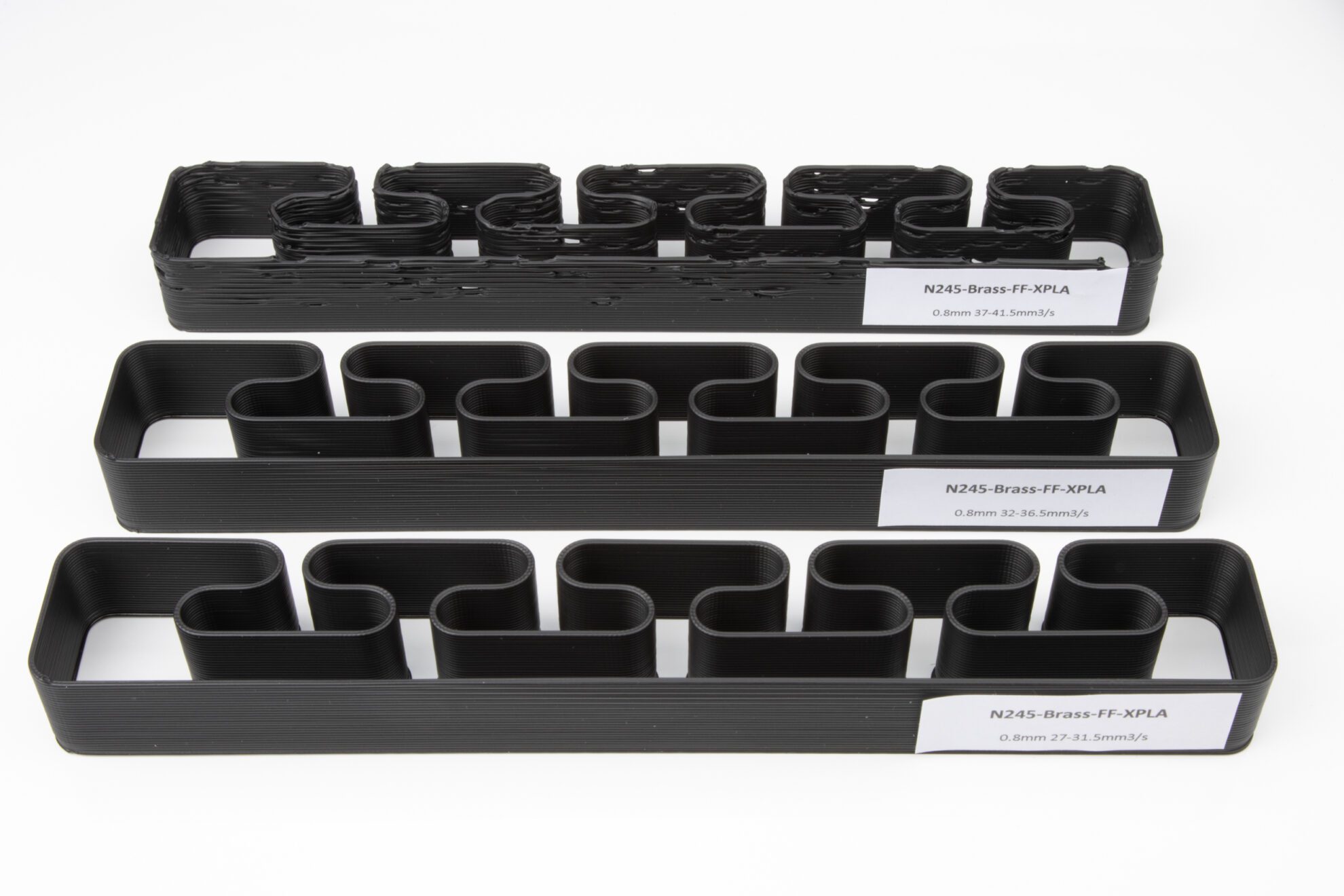
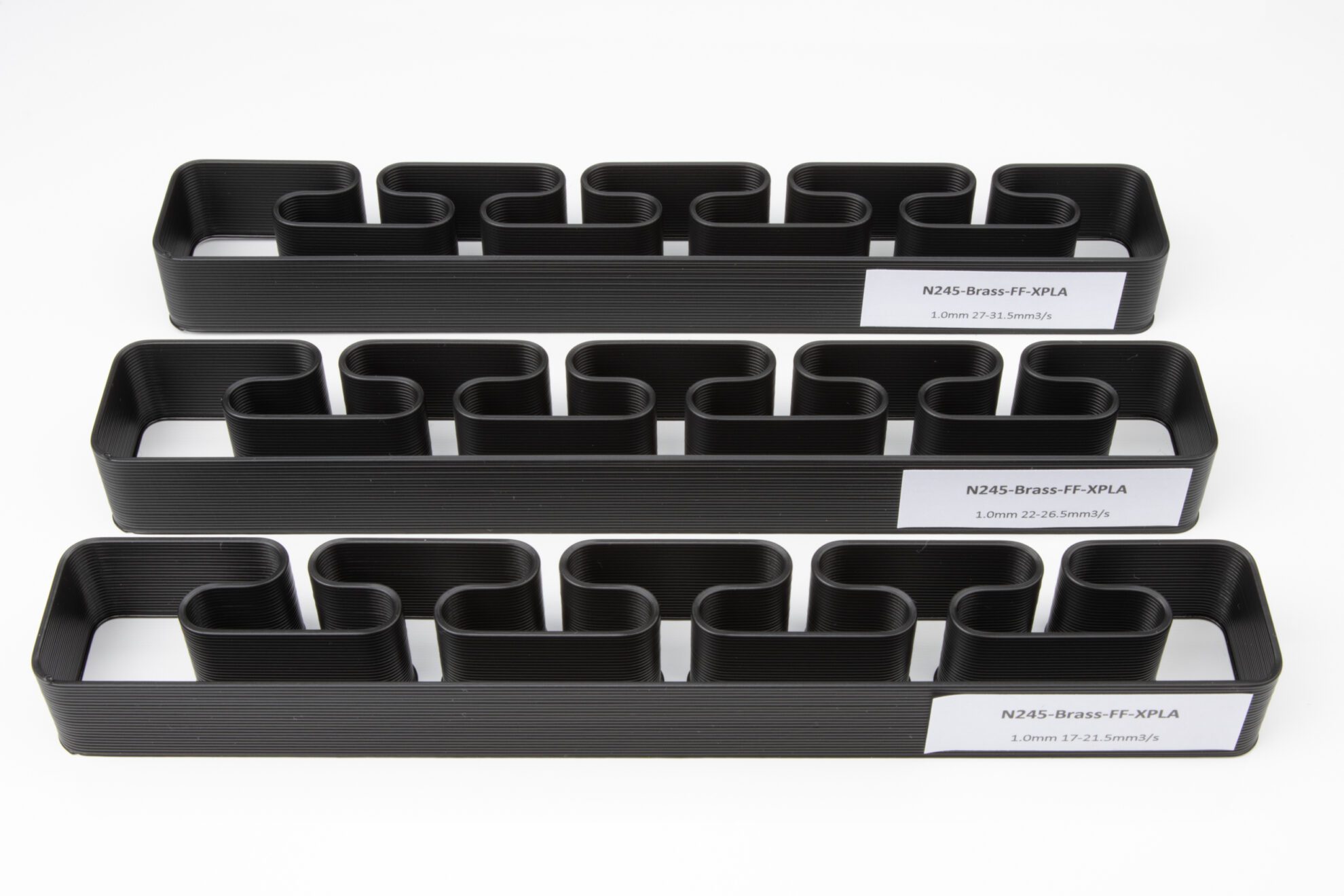
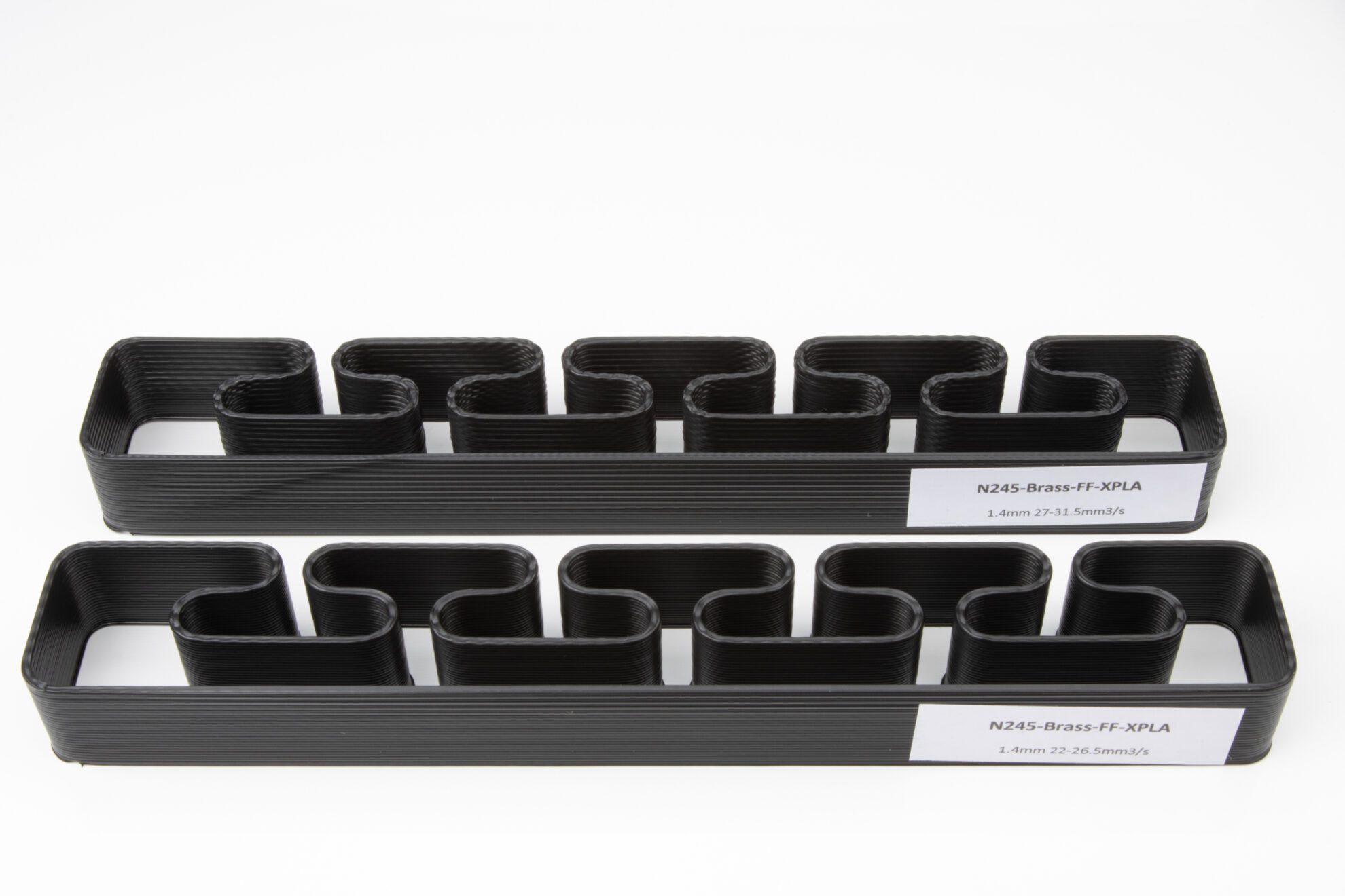
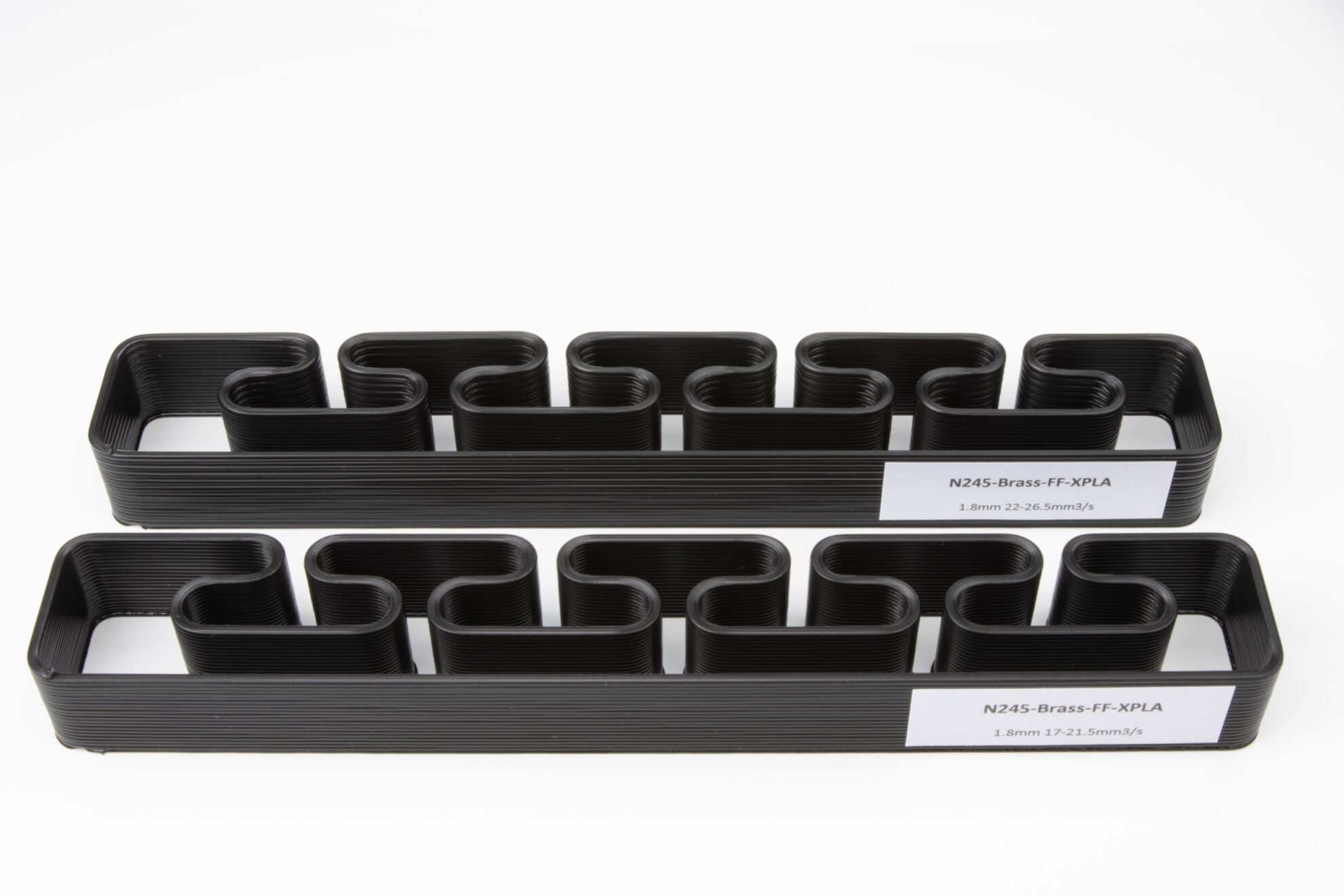
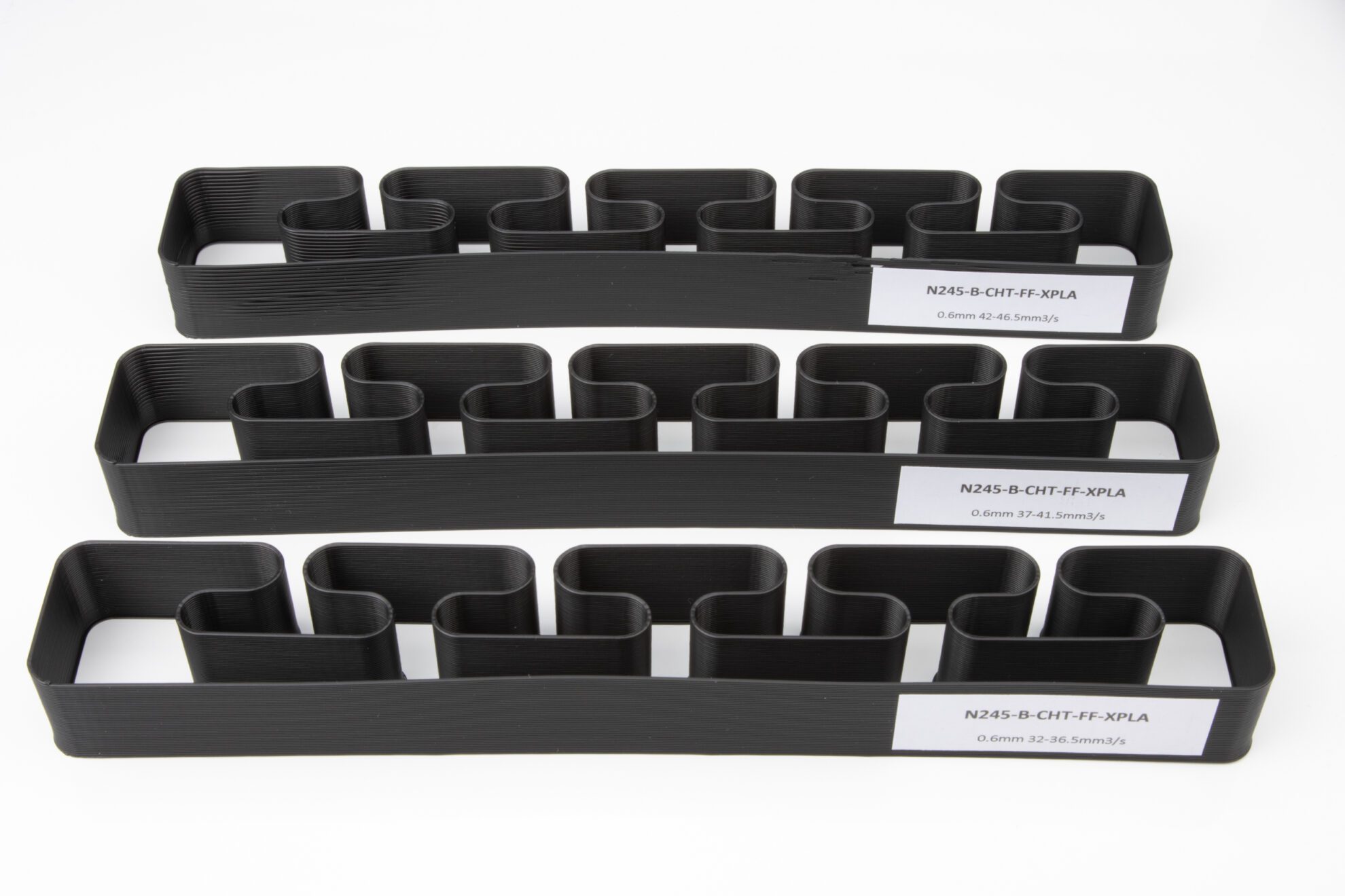
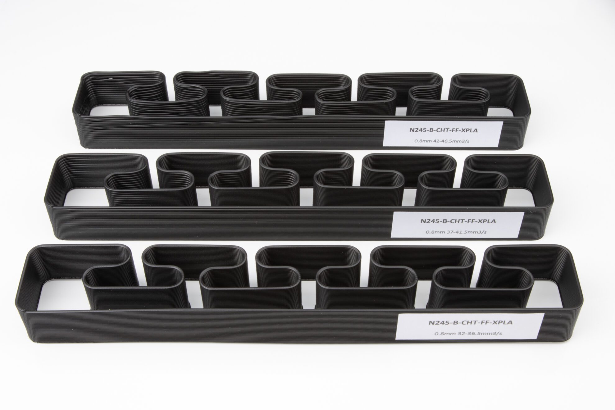
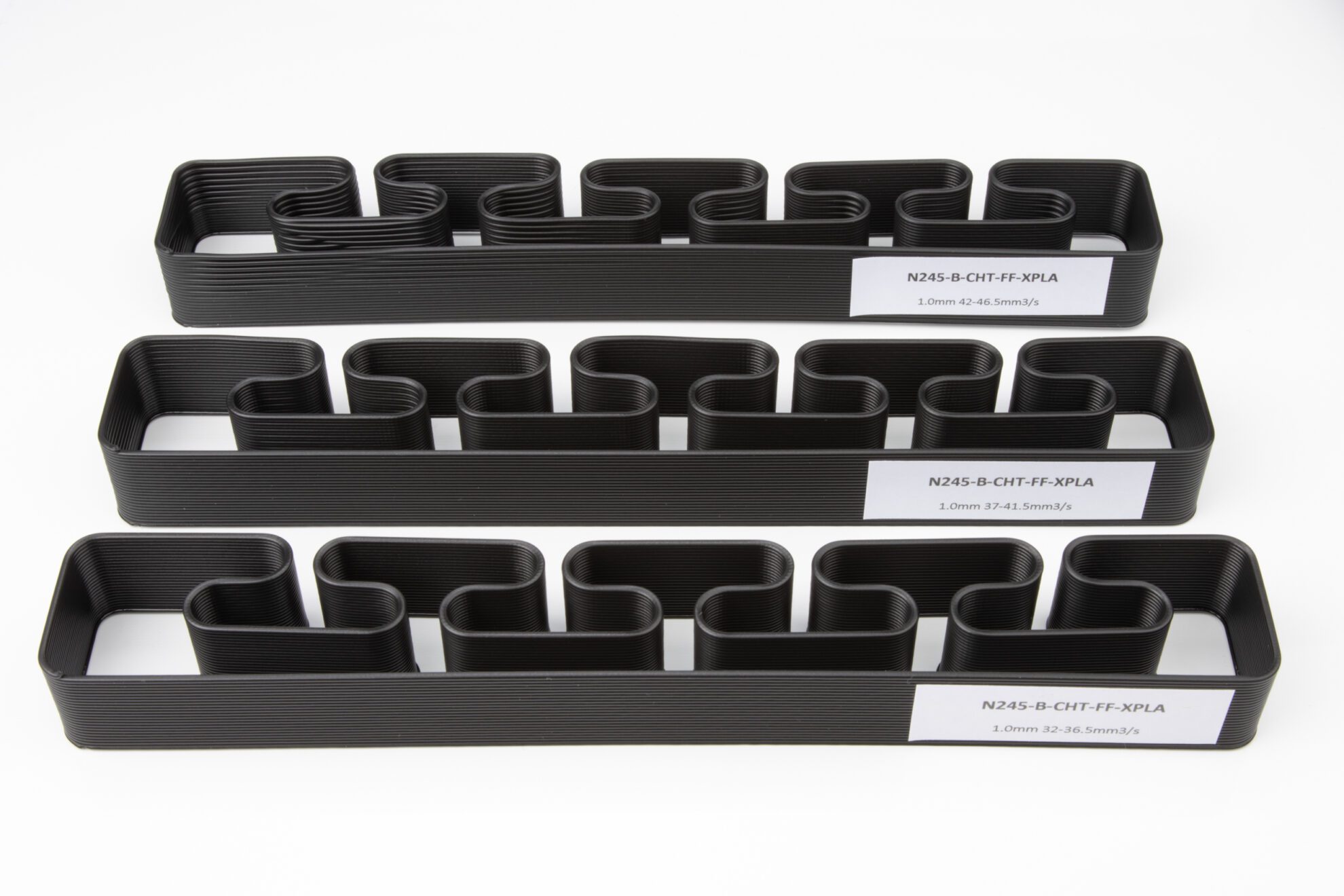
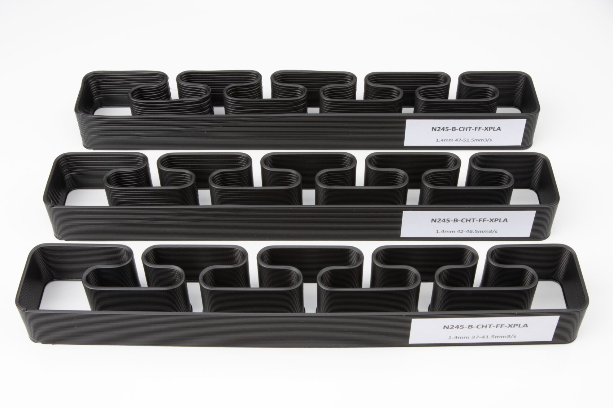
This study turns to a specific element of the equation, the nozzle, to find out what is the amount of its influence on the melt capacity of a hotend, and focus especially on the size, the temperature and the inlet geometry of the nozzle.

Purpose

To find out how much the orifice diameter, the temperature and the optimized inlet geometry of the nozzle impact the limits imposed by thermodynamics on the melt capacity of a hotend.

DESCRIBING THE TEST PROTOCOL

What are we testing?

The test protocol is used to measure the impact of the nozzle size, temperature, and inlet geometry on the hotend melt capacity by measuring the achieved max Volumetric Flow Rates of each nozzle temperature / size / type combination.

Who produced prior useful information?

This test protocol was inspired by Slice Engineering’s “Mosquito Magnum+ 1.75 Maximum Practical Flow Rate Test” White Paper; calculates Volumetric Flow rate according to Slic3r’s Advanced Flow Math to match with Prusa’s Slicer; and uses as starting points for testing, the nozzle and bed temperatures recommended by the materials’ manufacturer.

How is the protocol implemented?
  1. The protocol starts on an Excel spreadsheet. This document has different pages each devoted to a specific nozzle orifice diameter. In each page, snippets of G-code – grouping 10 consecutive target Volumetric Flow Rates paced at 0.5mm3/s – are calculated from a target layer height, extrusion width and starting Flow Rate.
  2. The G-code is pasted on the Slicer’s “Before layer change G-code” Custom G-code section.
  3. This calculated code inserted in the slicing process creates the growing percental jumps in “Speed For Print Moves” that correspond to 0.5mm3/s Flow Rate marginal increase for each 2mm of part height.
  4. A specific solid geometry with 20mm in height is sliced in vase mode using the same base print profile.
  5. For each print, the only profile’s parameters that are subject to change are the layer height, extrusion width, nozzle orifice diameter and temperature.
  6. The part is 3d printed using the selected material for each combination of nozzle temperature (T; T+20; or T+40); nozzle diameter (0.6; 0.8; 1.0; 1.4; or 1.8 mm); and nozzle inlet geometry (standard or CHT inlet).

These 3 nozzle temperature settings to test are indexed to T, where T is the Nozzle Temperature recommended by the materials’ manufacturer

The printed parts are inspected using 2 different criteria to identify a failure:

  1. Was there any layer that showed poor layer adhesion or warping? Answering Yes identifies a failure.
  2. Is there any layer showing visible signs of under extrusion? Answering Yes identifies a failure.

If a part is successfully printed – no failure is identified – a new part follows using the next Flow Rate interval. The occurrence of a failure ends the test series. The max Volumetric Flow Rate achieved is determined by identifying at which layer the first failure occurred. That layer is associated to a specific Flow Rate that becomes the max Volumetric Flow Rate of the (nozzle size / type / temperature and material) combination.

The results are stored in data tables that are used to create the comparison charts and support the conclusions.

Printer: Prusa i3 MK3s
Printhead: LGX® Shortcut Copperhead™
(a.k.a. LGX® FF or LGX® For Flexibles)
Nozzles: 0.6, 0.8, 1.0, 1.4, 1.8 Brass / CHT
Slicer: PrusaSlicer 2.3.1
Heater: Bondtech® 50W
Ambient temperature: 23°C
Flow Rate Calculus: Slic3r’s FlowMath

Why Was This Setup Chosen

The Prusa i3 MK3S was chosen for being within the top sold models and for belonging to such a reliable and well supported ecosystem of hardware, firmware and slicer software.

The LGX® extruder was a choice decided by its balance between grip power and push force and capacity for repeatability, both contributing for the reliability of the max Volumetric Flow Rate analysis.

The Copperhead™ hot block was selected for its known melt capacity and good performance, at the low end of blocks capable to support high flow applications.

The Bondtech 50W was selected to improve on the stock setup heating capacity in order to avoid the heater being a limitation.

Material: X-PLA
Diameter: 1.75 mm
Color: Black
Manufacturer: add:north
Features: X-PLA is a unique PLA-mix developed by add:north. It’s produced using 100% biodegradable material and has a high impact resistance, zero brittleness and an unbeatable surface finish.

Why Was This Material Chosen

PLA is one of the most popular non-abrasive materials. It was selected for the study to be relevant to as much people as possible, and apply to the most frequent applications.

Starting print temperature (T), set according to manufacturer recommended print settings for the specific filament.
205°C for X-PLA.

Temperature: T; T+20; T+40
Fan speed: 100%
Spiral vase: Yes
Extrusion width: 0.9; 1.4; 1.5; 1.68; and 2.16mm
Layer height: 0.48; 0.68; 0.80; 0.70; and 0.90mm
Layer change .gcode: used to increase flow rate every 2 mm on a 20mm high object.

Why Was This Setup Chosen

The extrusion width and layer height are chosen to optimize the relation between print speed and part cooling to reduce their impact in the equation.

Small nozzles require higher print speed to achieve target volumetric flow rate and therefore increased extrusion width and layer height help to reduce the printer kinematics impact on the test results.

The layer changing G-code was used to minimize the tests time consumption, allowing to sample multiple Volumetric Flow Rates in each test object.

Melt Capacity White Paper - Test Object

The test objects, printed using all different nozzle orifice diameters, are single wall perimeters made from printing in vase mode a model created as a flat solid body with 20mm in height, featuring multiple curves at different distances from each other.

Why Was This Model Chosen

The test object model was designed to put layer adhesion – with the curved sections – and max print speed – with the long straight path – under stress and test. Because it is printed using vase mode, its perimeter length was designed long enough to allow the necessary time for the material to cool down before a new layer is deposited, even when pushing a lot of material.

VOLUMETRIC FLOW RATE TEST RESULTS

Above are the summary charts, divided by nozzle temperature, with the results achieved with our “Max Volumetric Flow Rate Before Failure” tests showing the combined effect of nozzle orifice diameter and inlet geometry.

Below you can navigate all the result details of each test and check pictures of all samples created along the process. This information also provides useful intel on how to use the nozzle variables to improve build throughput.

Nozzle : Bondtech® Brass
Nozzle Size Extrusion Width (mm) Layer Height (mm) Speed (mm/s) Volumetric Flow Rate (mm3/s)
0.6 0.90 0.48 51 19.5
0.8 1.40 0.68 29.3 25
1.0 1.50 0.80 19.8 21
1.4 1.68 0.70 19.6 21
1.8 2.16 0.90 11.9 21
Nozzle : Bondtech CHT® Brass
Nozzle Size Extrusion Width (mm) Layer Height (mm) Speed (mm/s) Volumetric Flow Rate (mm3/s)
0.6 0.90 0.48 79.7 30.5
0.8 1.40 0.68 38.1 32.5
1.0 1.50 0.80 34.3 36.5
1.4 1.68 0.70 36 38.5
1.8 2.16 0.90 22.9 40.5
Nozzle : Bondtech® Brass
Nozzle Size Extrusion Width (mm) Layer Height (mm) Speed (mm/s) Volumetric Flow Rate (mm3/s)
0.6 0.90 0.48 52.3 20
0.8 1.40 0.68 30.5 26
1.0 1.50 0.80 23.1 24.5
1.4 1.68 0.70 22.9 24.5
1.8 2.16 0.90 13 23
Nozzle : Bondtech CHT® Brass
Nozzle Size Extrusion Width (mm) Layer Height (mm) Speed (mm/s) Volumetric Flow Rate (mm3/s)
0.6 0.90 0.48 86.3 33
0.8 1.40 0.68 44.6 38
1.0 1.50 0.80 36.2 38.5
1.4 1.68 0.70 36.4 39
1.8 2.16 0.90 23.4 41.5
Nozzle : Bondtech® Brass
Nozzle Size Extrusion Width (mm) Layer Height (mm) Speed (mm/s) Volumetric Flow Rate (mm3/s)
0.6 0.90 0.48 56.2 21.5
0.8 1.40 0.68 34.6 29.5
1.0 1.50 0.80 24 25.5
1.4 1.68 0.70 23.3 25
1.8 2.16 0.90 13.3 23.5
Nozzle : Bondtech CHT® Brass
Nozzle Size Extrusion Width (mm) Layer Height (mm) Speed (mm/s) Volumetric Flow Rate (mm3/s)
0.6 0.90 0.48 92.8 35.5
0.8 1.40 0.68 44.6 38
1.0 1.50 0.80 35.8 38
1.4 1.68 0.70 40.2 43
1.8 2.16 0.90 24.9 44

Differential Analysis

This is another way to look at the same results using the same data to find answers to the question:
What is the impact each variable brings on its own to the increase of “Max Volumetric Flow Rate Before Failure”?

Orifice Diameter
Volumetric Flow Rate Gain (%)

(using +0.4mm steps)

Average increase : +6.2%

When using the same nozzle temperature and inlet geometry what happens to the maximum Volumetric Flow Rate when we raise nozzle orifice diameter from 0.6 to 1.0; from 1.0 to 1.4; and from 1.4 to 1.8mm. Values presented are the marginal percentual variations.

205°C 225°C 245°C
standard
0.6 to 1.0 mm
+7.7% +22.5% +18.6%
standard
1.0 to 1.4 mm
+0.0% +0.0% -2.0%
standard
1.4 to 1.8 mm
+0.0% -6.1% -6.0%
CHT
0.6 to 1.0 mm
+19.7% +16.7% +7.0%
CHT
1.0 to 1.4 mm
+5.5% +1.3% +13.2%
CHT
1.4 to 1.8 mm
+5.2% +6.4% +2.3%

Temperature
Volumetric Flow Rate Gain (%)

(using +20°C steps)

Average increase : +6.8%

Temperature related Volumetric Flow Rate gain (%)

When using the same nozzle orifice diameter and inlet geometry what happens to the maximum Volumetric Flow Rate when we raise nozzle temperature from 205 to 225; and from 225 to 245°C. Values presented are the marginal percentual variations.

0.6mm 0.8mm 1.2mm 1.4mm 1.8mm
standard
205 to 225°C
+2.6% +4.0% +16.7% +16.7% +9.5%
standard
225 to 245°C
+7.5% +13.5% +4.1% +2.0% +2.2%
CHT
205 to 225°C
+8.2% +16.9% +5.5% +1.3% +2.5%
CHT
225 to 245°C
+7.6% +0.0% -1.3% +10.3% +6.0%

Inlet Geometry
Volumetric Flow Rate Gain (%)

(changing from standard to CHT)

Average increase : +63.1%

When using the same nozzle temperature and nozzle orifice diameter what happens to the maximum Volumetric Flow Rate when we change the inlet geometry from standard to the new CHT. Values presented are the marginal percentual variations.

205°C 225°C 245°C
0.6mm
Standard to CHT
+56.4% +65.0% +65.1%
0.8mm
Standard to CHT
+30.0% +46.2% +28.8%
1.0mm
Standard to CHT
+73.8% +57.1% +49.0%
1.4mm
Standard to CHT
+83.3% +59.2% +72.0%
1.8mm
Standard to CHT
+92.9% +80.4% +87.2%

VOLUMETRIC FLOW RATE TESTS DISCUSSION

To pursue a good level of accuracy and repeatability several test parameters were stabilized.

  • Fixed variables;
  • Quality filament used;
  • Same setup, swap one parameter makes clear improvement;
  • All tests done with the same MK3S unit.

Every printer has a different fingerprint. Tests with two different units were made and when compared showed slightly different results even though they are seemingly the same. This may be due to tolerances of components, quality of materials, and/or assembly processes. For this reason a single printer was selected and the same hardware was used on all tests, only changing nozzles.

There is currently no industry standard for determining good / acceptable quality of a print. Together with the results above, we present 2 or 3 printed test objects showing the results from the progressive increase of Flow Rate until quality degrades from “good” to failure.

The results presented in the tables and charts are measured and registered at the point when any abnormalities occur, such as signs of under extrusion or insufficient interlayer adhesion resulting in part warping.

Some test sets that presented results seemingly abnormal were repeated for confirmation.

Filament pushed out too fast through larger nozzles tends to not properly get its core heated up and is extruded “cold”. Slice Engineering refers to this as “The cool center effect” in their “Mosquito Magnum+ 1.75 Maximum Practical Flow Rate Test ” White Paper. This leads to poor perimeter and layer adhesion.

The results of this study, and the examination of the printed test parts, show that Bondtech CHT® nozzles increase performance with larger nozzles, while standard nozzles suffer from growing “layer bonding issues”.

See example in the following image (click to zoom in) >

This can be explained by the absence of the “cool center effect” on the Bondtech CHT® nozzles as their three inlet channels split the filament and melt it down from the center.

The print tests are performed with filament manufacturer’s recommended print setting as a starting point. For X-PLA, 205°C on the nozzle and 70°C on the bed is add:north‘s recommendation.

During visual inspections of the parts it is clear the bed temperature has a big impact on the first layers bonding. Even with the part cooling fan set on max, the lower layers of the print maintain a higher temperature that improves the bonding between them, avoiding failures that may occur further up, away from the bed.

This effect is mostly evident when a series of printed test parts show “good” sections of lower layers in between top and middle layers showing failures.

See example in the following image (click to zoom in) >

This study does not address any other nozzle related impact source – outlet geometry; material; surface coating, etc. – and its implementation is focused on a specific hardware setup based on the Prusa MK3S 3D printer and the LGX® Shortcut Copperhead™ printhead with a 50W Bondtech® heater.

The test protocol implementation only covers printing using vase mode, in a continuous way, without retractions or non-print moves (travel).
The study findings depend on visual inspection of the parts and do not include any sort of part mechanical or chemical properties analysis.

The results were also constrained by other factors. Check “Part Cooling Capacity” below.

It is noticeable in the study that part cooling capacity becomes a limitation when the Volumetric Flow Rates tested reach values close to 40mm3/s. The evidence is an unexpected decline or reversal of the marginal gains when reaching those top Flow Rate combinations. Failures observed then are consistent with swelling and wobbling caused by too slow cool down of the deposited material.

Conclusions

Lessons from the study

Nozzle orifice diameter and temperature have a positive impact on increasing the melt capacity of a hotend.

For high flow applications using standard inlet geometries with this setup, the 0.8mm orifice diameter is the sweet spot.

The change from standard to CHT inlet geometry has a significant impact on the growth of melt capacity and it is very scalable with no specific sweet spots identified on what regards to nozzle orifice diameter.

The heated bed has a positive impact on the reliability of the extrusion, especially on the lower layers. This effect can be used to push higher the Volumetric Flow Rate on low and flat parts.

To check out the Bondtech CHT nozzles click here.


How to Increasing Melt Capacity with 3 key nozzle features

Selecting the right nozzle orifice diameter for a specific application and using the CHT inlet geometry is the starting point. On high flow applications, where the limits of the hotend are reached, overshooting the nozzle temperature above the manufacturer’s recommendation is also required to compensate for the additional intake of cold material into the hot block and nozzle.

The right combination of these 3 factors will push up the current limits of the hotend, and the gains can be very relevant and even surprising.

APPENDIX

Download documents and other files used to prepare and perform the tests on this White Paper.

Download .stl

STL File

Archive with the mesh of the test object

Download .xlsx

Excel File

Archive with the spreadsheet with the G-code generator.

Download .gcode

G-code Files

Archive with the collection of the g-code files.

Download .3MF

Project Files

Archive with the collection of Prusa Slicer Projects.

Want to know more?

Register yourself or login to leave a Question, Reply or Comment in the section below.

If you didn't already, you can also subscribe to our newsletter to receive the short updates about our new products, updates or technology on your mailbox.

Thank you : )

Leave a Reply